


5-7 SOURCE/TEST
SET/RECEIVER
Because of the 373XXA phase-lock loop structure, it is not easy to distin
-
guish between failures that occur in the Source Module, the Test Set
Module and the Receiver Module. In order to troubleshoot failures occur
-
ring in this group of modules, it is essential to be familiar with how each
module functions and how it interacts with the other modules. Refer to
Chapter 7, System description, for a functional description of each mod
-
ule.
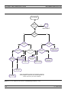
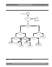
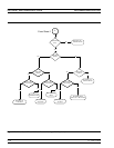
For Model 37397A, refer to Figure 5-3 and Figure 5-4 (rear of section)
for aid in troubleshooting Test and Source Lock signal paths. Refer
also to Table 5-6 (rear of section) for a list of typical reference signal
values, and to Tables 5-7 and -8 for Transfer and DPDT Switch Volt
-
ages.
Signal Source Phase
Lock Loop Assemblies
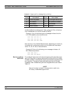
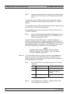
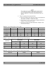
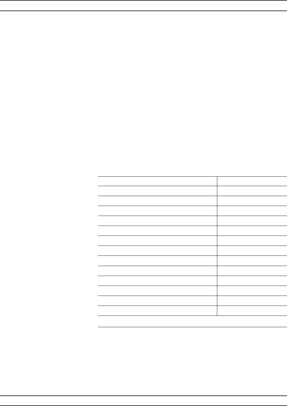
The 373XXA assemblies that contain circuits that are part of the sig
-
nal source phase-lock loop (Source Lock function) are listed in Table
5-4.
Failures occurring in the Source Module, Test Set Module and Re
-
ceiver Module will generally cause the system to produce “Phase Lock
Fail” error codes. Included with the Phase Lock Fail error codes are al
-
phabetical suffixes that indicate the probable malfunctioned
sub-assembly.
Example: 6008 PHS LCK FAIL D
TROUBLESHOOTING SOURCE/TEST SET/RECEIVER
373XXA MM 5-17
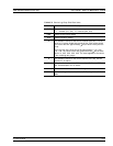
Assemblies Location
A21A1 Source YIG/Bias PCB Source Module
A21A2 Source Control Source Module
YIG Oscillator Source Module
Switched Filter Source Module
Down Converter Source Module
Switched Doubler Module SDM* Test Set Module
Transfer Switch Test Set Module
Buffer Amplifier Receiver Module
A1 LO1 PCB Receiver Module
A2 LO2 PCB Receiver Module
A4 Reference IF PCB IF Section
A8 Source Lock/Signal Separation Control PCB Analog Subsystem
A9 Main Processor PCB Digital Subsystem
∗ Model 37369A only, ** See Figure 5-4 for 37397A models
Table 5-4. Phase Lock Loop Assemblies**