


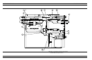
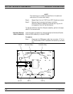
NOTE
The matching pin numbers are identified on the cable con
-
nectors and on the connector body.)
Step 4. Repeat Step 3 for the TEST B and REF B cable connectors.
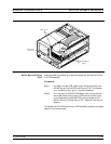
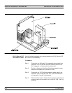
Step 5. Remove the nine screws that fasten the Buffer
Amplifier/Sampler assembly to the test set tray, and lift
the assembly from the Test Set Module.
To replace the Buffer Amplifier/Sampler assembly, perform the steps
above in the reverse order.
Switched Doubler
Module Assembly
Use the following procedure to remove/replace the Switched Doubler
Module (SDM) assembly for Model 37269B.
Procedure:
Step 1. Disconnect the SDM power cable from connector J17 of the
A17 Motherboard PCB. Free cable from cable clip, as neces-
sary.
TEST SET MODULE ASSEMBLIES REMOVE AND REPLACE
8-28 373XXA MM
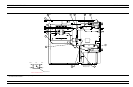
REF A
Connector Body
A31J8
REF A
A31J10
W132
J1
J2
J3
J4
J5
J6
J7
W145
REF A
REF B
TEST A
TEST B
TEST A
Connector Body
TEST A
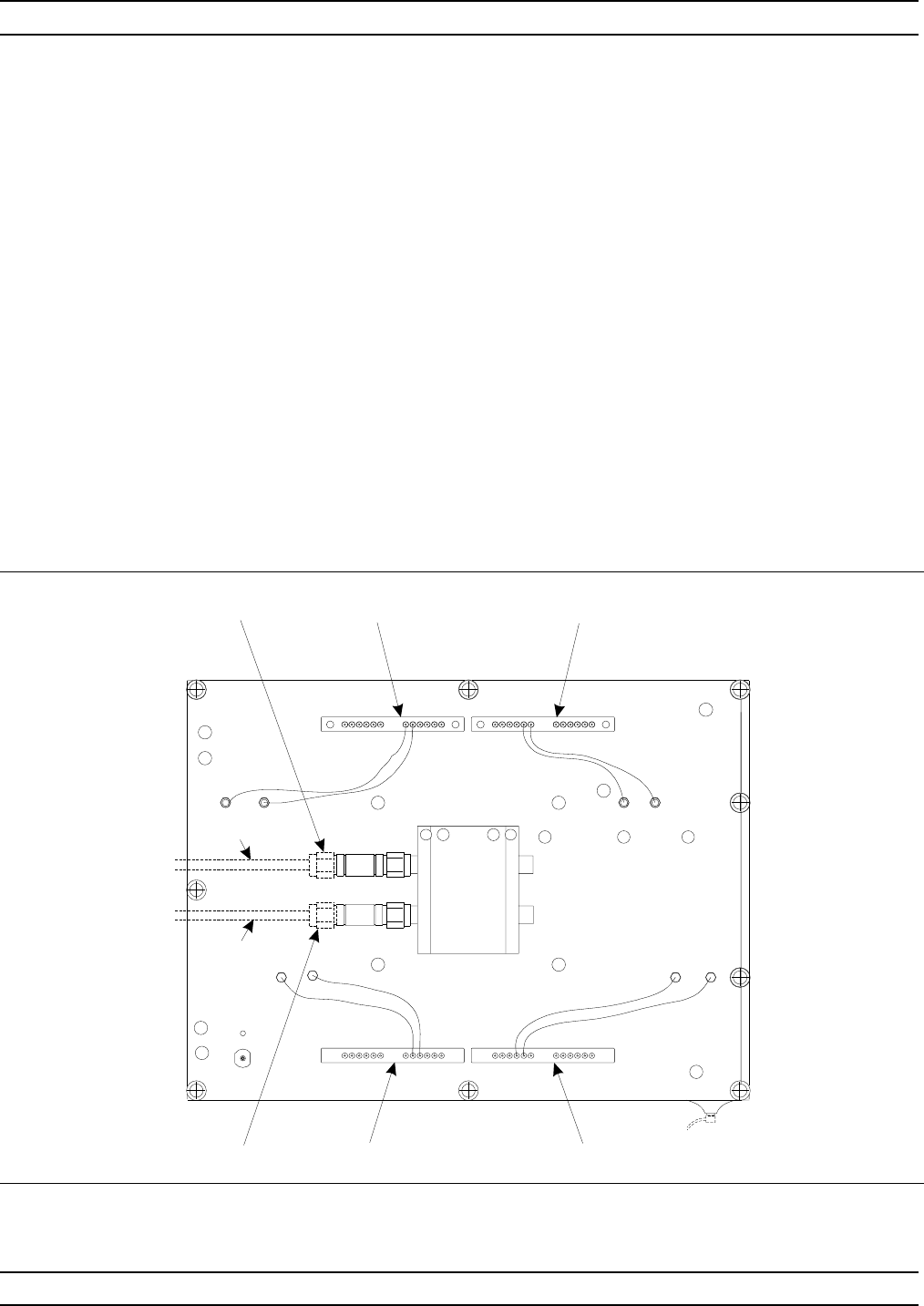
Figure 8-14. A31 Buffer Amplifier/Sampler Assembly, Details