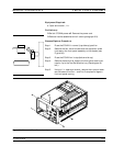
work surface. Remove cables from cable harnesses, as re
-
quired.
To replace the Rear Panel Assembly, perform the steps above in the re
-
verse order.
8-13 FAN ASSEMBLY This paragraph provides instructions for removing and replacing the
Rear Panel Fan Assembly.
Preliminary:
q
Switch373XXA power off. Remove the power cord.
q
Remove all covers (paragraph 8-3).
q
Remove Rear Panel (paragraph 8-12).
Remove/Replace Procedure:
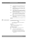
Step 1. Place the Rear Panel Assembly on the work surface with
the A18 Rear Panel PCB up.
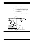
Step 2. Disconnect the two conductor fan power cable at connector
P6 of the A18 PCB.
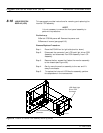
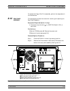
Step 3. Turn Rear Panel Assembly over, and remove the four
screws that fasten the fan guard and fan assembly to the
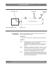
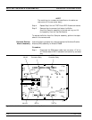
rear panel. See Figure 8-10.
Step 4. Remove the fan guard and separate the fan from the rear
panel.
To replace the Rear Panel Fan Assembly, perform the steps above in
the reverse order.
8-14 POWER SUPPLY
MODULE
This paragraph provides instructions for removing and replacing the
Power Supply Module.
Preliminary:
q
Switch373XXA power off. Remove the power cord.
q
Remove all covers (paragraph 8-3).
q
Remove Rear Panel (paragraph 8-12).
Remove/Replace Procedure:
Step 1. Place the Rear Panel Assembly on the work surface with
the Power Supply Module down.
REMOVE AND REPLACE FAN ASSEMBLY
373XXA MM 8-21


