


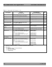
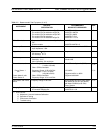

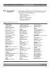

GENERAL INFORMATION RECOMMENDED TEST EQUIPMENT
373XXA MM 1-11
INSTRUMENT
CRITICAL
SPECIFICATION
RECOMMENDED
MANUFACTURER/MODEL
USE*
*
Assurance Air Line For models 37317A and below w/Opt 7A:
For models 37317A and below w/Opt 7N:
For models 37317A and below w/Opt 7NF:
For models 37317A and above:
For models 37317A and below w/Opt 7S:
ANRITSU 18A50
ANRITSU 18NF50
ANRITSU 18N50
ANRITSU T1519
ANRITSU T1147-2
P
Offset Termination For models 37317A and below w/Opt 7A, 7N,
7NF:
All other models
ANRITSU 29A50-20
ANRITSU 29KF50-15
P
Frequency Counter Frequency: 0.1 to 26.5 GHz
Input Impedance:50Ω
EIP Microwave, Inc., Model 578B
P, A
Digital Multimeter Resolution: 4
1
2
digits
DC Accuracy: 0.1 %
AC Accuracy: 0.1 %
Any
T
Oscilloscope Bandwidth: DC to 100 MHz
Sensitivity: 2mV
Horiz. Sensitivity: 50 ns/division
Tektronix, Inc.
Model 2445
T
Power Meter 1, with: Power Range: –30 to +20 dBm
(1 mW to 100 mW)
Other: GPIB controllable
HP 437B with Option 22 (GPIB)
P, A
Power Sensor 1
or:
Power Meter 2, with:
Power Sensor 2
Frequency Range: 0.05 to 50 GHz
Power Range: –70 to +47 dBm
(100 pW to 50 W)
Other: GPIB controllable
Frequency Range: 0.01 to 40 GHz
HP 8487A
Gigatronics 8541 or 8542
Gigatronics 80304A
P, A
Power Meter and Power
Sensor
Frequency Range: to 65 GHz Anritsu Model ML24xxA Power Meter
and MA2474A (40 GHz and below)
and Model SC6230 (to 65 GHz)
Power Sensors
P, A
Gauging Set GPC-7 Gauging Set
K Connector Gauging Set
ANRITSU 01-161
ANRITSU 01-162
O, T
∗∗ USE CODES:
A Adjustment / Internal Hardware Calibration
O Operational Testing
P Performance Verification
T Troubleshooting
Table 1-1. Recommended Test Equipment (2 of 2)