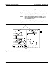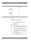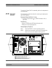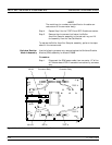
Step 2. Remove the six screws from the rear panel that fasten it to
the left and right edges of the Power Supply Module (see
Figure 8-10). Gently separate the two units.
To replace the Power Supply Module, perform the steps above in the
reverse order.
8-15 A18 REAR PANEL PCB This paragraph provides instructions for removing and replacing the
A18 Rear Panel PCB assembly.
Equipment Required:
q
Nut Driver,
9
32
in.
q
Nut Driver,
3
16
in.
Preliminary:
q Switch373XXA power off. Remove the power cord.
q Remove all covers (paragraph 8-3).
q Remove Rear Panel (paragraph 8-12).
Remove/Replace Procedure:
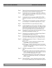
Step 1. Place the Rear Panel Assembly on the work surface with
the A18 Rear Panel PCB up.
Step 2. Disconnect the two-conductor fan power cable at connector
P6 of the A18 PCB.
Step 3. Disconnect the wiring for the rear panel Bias Fuses at con
-
nector P4 of the A18 PCB.
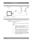
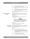
Step 4. Turn Rear Panel Assembly over. Remove screw located at
lower left corner of the rear panel that fastens the A18
PCB to the Rear Panel Assembly (see Figure 8-10).
Step 5. Using a
9
32
in. nut driver, remove the standoffs that fasten
the IEEE 488.2 GPIB and Dedicated GPIB connectors to
the rear panel.
Step 6. Using a
3
16
in. nut driver, remove the standoffs that fasten
the Printer Out, VGA Out, and External/IO connectors
to the rear panel. Set standoffs aside for re-use.
Step 7. Carefully separate the A18 PCB from the rear panel.
To replace the A18 Rear Panel PCB assembly, perform the steps above
in the reverse order.
A18 REAR PANEL PCB REMOVE AND REPLACE
8-22 373XXA MM


