


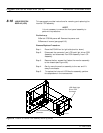
Equipment Required:
q
Open-end wrench, 1 in.
Preliminary:
q
Switch 373XXA power off. Remove the power cord.
q
Remove handle assembles and all covers (paragraph 8-3).
Remove/Replace Procedure:
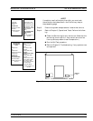
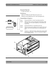
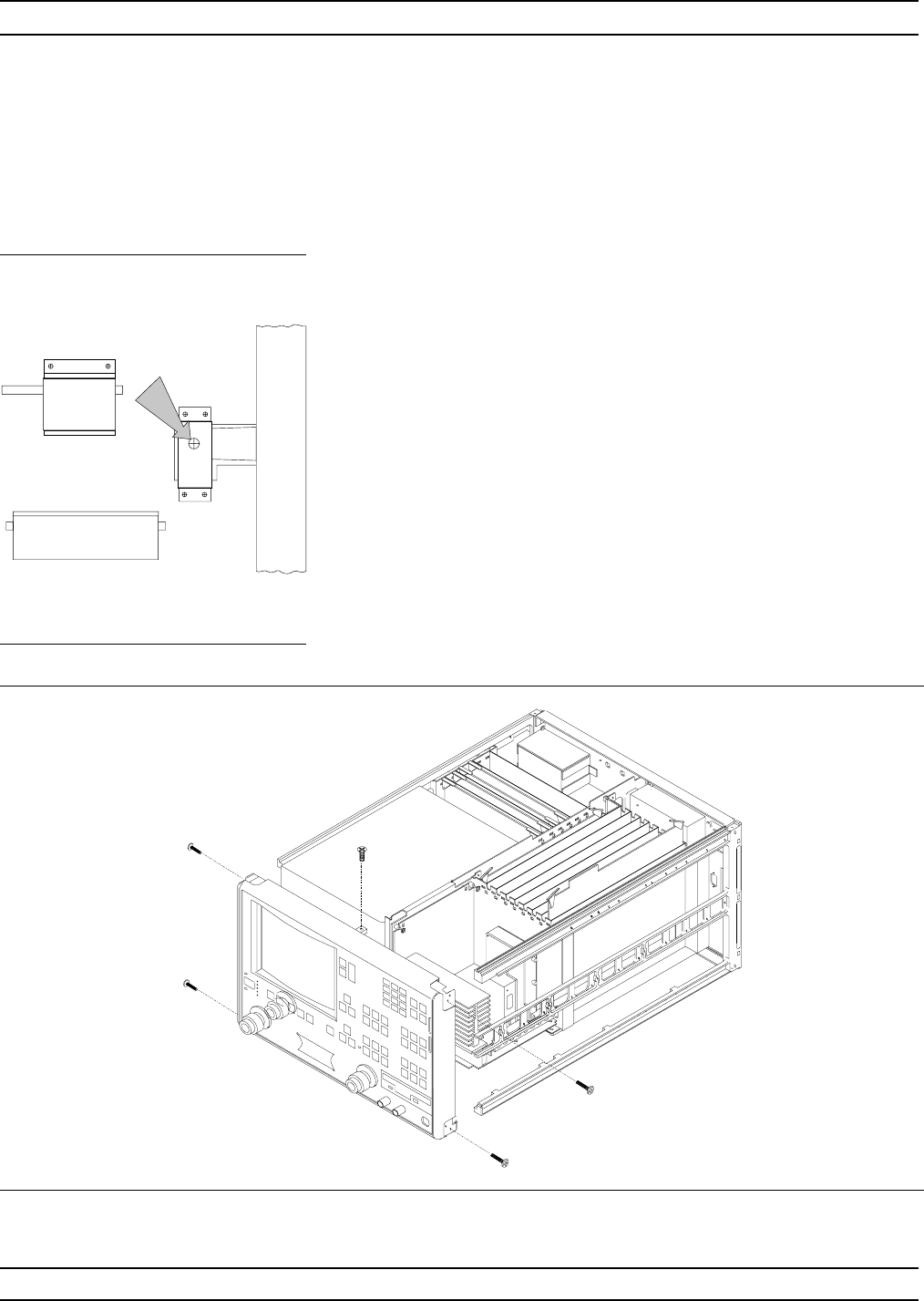
Step 1. Place the 373XXA in normal (top-side up) position.
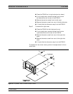
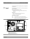
Step 2. Remove the four corner screws and the top center screw
that secure the front panel assembly to the chassis (see
Figure 8-6).
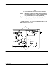
Step 3. Place the 373XXA on its top (bottom-side up).
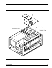
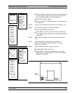
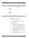
Step 4. Remove the screw that fastens the front panel casting ex-
tension lip to the Test Set Module tray. (See diagram at
left.)
Step 5. Using a 1 in. open-end wrench, remove the nuts and wash-
ers that secure the Port 1 and Port 2 couplers/bridges to
the front panel casting.
REMOVE AND REPLACE FRONT PANEL ASSEMBLY
373XXA MM 8-13
Figure 8-6. Removal of Front Panel Assembly