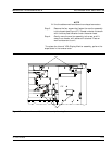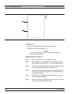
Step 6. Locate the cable from the front panel Power switch to con
-
nector J20 on the A17 Motherboard PCB. Disconnect at
A17, J20 end.
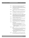
Step 7. Locate the cable from the front panel Keyboard interface
connector to connector J16 on the A17 Motherboard PCB.
Disconnect at A17, J16 end.
Step 8. Locate the cables from the front panel Bias Input BNC con
-
nectors to connector P2 on the A18 Rear Panel PCB. Dis
-
connect at A18, P2 end. (A18, P2 is the connector nearest to
the bottom lip of the rear panel.)
Step 9. Gently pull front panel assembly several inches away from
chassis. Locate cable from A17 Motherboard PCB to con
-
nector J1 on A20 Front Panel PCB. Disconnect at A20, J1
end.
Step 10. Separate the bias input cables (Step 8) from the cable har-
nesses, as necessary for removal. Pull front panel assembly
free and set aside.
To replace the front panel assembly, perform the steps above in the re-
verse order.
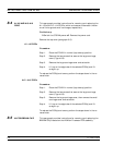
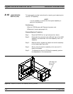
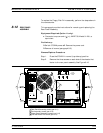
8-9 VGA DISPLAY MONITOR This paragraph provides instructions for removing and replacing the
internal VGA Display Monitor assembly.
NOTE
It is not necessary to remove the front panel assembly to
perform this procedure.
Preliminary:
q
Switch 373XXA power off. Remove the power cord.
q
Remove all covers (paragraph 8-3).
Remove/Replace Procedure:
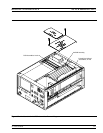
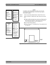
Step 1. Place the 373XXA on its right side (monitor down).
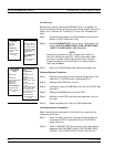
Step 2. At rear of monitor assembly, disconnect:
n
The power cord (from the Power Supply Module)
n
The data cable from motherboard CRT connector, J14
n
The two cables from motherboard BRITE/DEGAUSS
connector, J15.
VGA DISPLAY MONITOR REMOVE AND REPLACE
8-14 373XXA MM


