8-6 A9 PCB SRAM BATTERY This paragraph provides instructions for removing and replacing the
SRAM Battery located on the A9 Main Processor PCB assembly.
Preliminary:
q
Switch the 373XXA power off. Remove the power cord.
CAUTION
The SRAM battery incorporates flammable materials such
as lithium and organic solvents. If lithium batteries, such
as this one, are mistreated or incorrectly handled, they
may burst open and ignite. This can result in possible in
-
jury or fire. When handling the SRAM battery, carefully
following the following precautions:
•
DO NOT short circuit.
•
DO NOT disassemble, deform, or apply excessive pres
-
sure.
• DO NOT heat or incinerate.
• DO NOT apply solder directly.
• DO NOT mix model or new and old batteries.
• DO NOT charge.
• ALWAYS check that proper polarity is observed.
Remove/Replace Procedure:
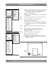
Step 1. Remove the top cover and the large card-cage cover to ex-
pose the A1 – A9 PCBs (refer to paragraph 8-4).
Step 2. Remove the A9 PCB from the unit.
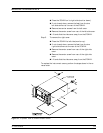
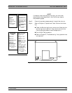
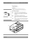
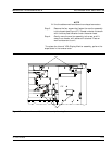
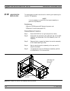
Step 3. Locate and carefully remove the SRAM battery from the A9
PCB. See Figure 8-4.
Step 4. Replace the SRAM battery on the A9 PCB, as follows:
- Insure that the pins are clean.
- Note the polarity and carefully press the batterly into
the socket.
Step 5. Reinstall the A9 PCB, the large card-cage cover, and the
top cover.
Post Replacement Procedure:
Step 1.
Connect power cord. Switch 373XXA power on.
Step 2. Ensure the system sweeps several times without errors.
Step 3. Refer to Chapter 3, Operational Tests. Perform the follow
-
ing:
A9 PCB SRAM BATTERY REMOVE AND REPLACE
8-10 373XXA MM


