4 Installing a New G700 without an S8300: Administer Communication Manager
196
Installation and Upgrades for G700 with S8300 or S8700
555-234-100 — Issue 3 — May 2003
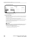
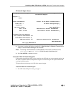
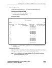
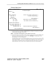
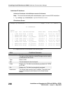
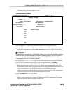
Example Node Names Screen.
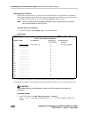
3. Enter the name and IP address for the C-LANs and LSPs.
4. Press F3 (ENTER) when complete.
Administer Network Regions
Before assigning an IP network region to a G700, you must define network region on the IP Network
Region form. After a network region is defined, you can assign it to the various network elements
(servers, gateways, IP phones).
The information you need to do this should be provided in your planning documentation. Use the
system defaults if the planning documentation does not specify otherwise.
For a G700 with an S8300 LSP and an S8700 as the primary controller, there may be more than one
network region, since there can be up to 250 G700 Media Gateways connected to the S8700 with
thousands of telephones in the network. In this case, you define a network region for each CLAN
board on the S8700 port networks, though they may also have the same network region.
The G700, in this case, may also share the same network region as the CLAN board(s). However, it
may have a different network region because of the geographic distances of the connections between
the G700 and the S8700. The G700 network region may also differ because of the nature of the
endpoints connected to it.
Define IP network regions for the G700 and CLAN board(s)
!
CAUTION:
Defining IP network regions can be quite complex. For detailed information on the use and
administration of IP network regions, see ‘‘Administration for Network Connectivity for
Avaya™ Communication Manager, 555-233-504.’’
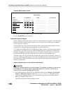
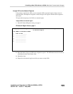
1. On the S8700 primary controller for the G700 Media Gateway, type change ip-network-
region <network_region>, where the <network_region> is the region you will
assign to the G700 Media Gateway. This region number may or may not match the network
region of the S8700 CLAN boards.
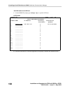
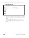
The S8700 displays the IP Network Region screen.
change node-names ip Page 2 of 2
NODE NAMES
Name IP Address Name IP Address
default_________ 0__.0__.0__.0__ _______________ ___.___.___.___
node-1-clan __
192.168.1 _.124 _______________ ___.___.___.___
node-2
-clan 192.168.1 _.97_ _______________ ___.___.___.___
node-10-lsp
192.168.1 _.50_ _______________ ___.___.___.___
node-11-lsp
192.168.1 _.51_ _______________ ___.___.___.___
_____
_____ ___.___.___. _ _______________ ___.___.___.___
_____
_____ ___.___.___. _ _______________ ___.___.___.___
_____
_____ ___.___.___. _ _______________ ___.___.___.___


