


Galaxy 65 User Guide
6
Caution All mandatory settings must be observed in order for the Galaxy 65 system to function correctly.
Note To set Host 1Gb use the Ethernet connected configurator.
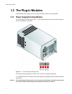
1.3.3 Loop Resiliency Circuit Input/Output Module (FC-AL)
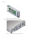
The Galaxy 65 storage Subsystem includes an enclosure with rear facing bays which house two Loop
Resiliency Circuit (LRC) I/O modules with integrated Rorke Data
Galaxy 65 RAID controller, known as
Storage Managers (SM) modules. (see Figure 1–3)
The FC-AL Backplane incorporates two independent loops formed by Port Bypass Circuits within the LRC
I/O modules.
The plug-in SM modules have been designed for integration into a Galaxy 65 storage Subsystem, utilizing
FCAL interfacing with the host computer system.
Processors housed on the LRC modules provide enclosure management and interface to devices on the
Backplane, PSU, LRC and Ops Panel, to monitor internal functions. These processors operate in a
master slave configuration to allow failover.
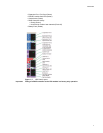
The module incorporates the following LED indicators, shown in Figure 1–7:
• Host Port 0 Signal Good (Green)
• Host Port 1 Signal Good (Green)
• Expansion Port 0 Rx Good (Green)
Table 1–1 Ops Panel Switch Functions (Default settings for Galaxy 65 LRC usage at 2Gb/s)
Switch
Number
Function Recommended
Setting
Definition
1 Loop Select,
Dual (2x8)
Off LRC operates on two loops of 8 drives
Mandatory
2 Not Used Note: on Galaxy 65-FC2 enclosures this must be set On.
3 Not Used
4 Not Used
5 & 6 Not Used
7 & 8 Drive Loop Speed
Select
Sw7 Sw8
On Off Force 2Gb/s
Off Off Force 1Gb/s
9 & 10 Drive Addressing
Mode Selection
Sw9 Sw10
On Off Mode 2, 2x8 mode. Mandatory
11 SOFT SELECT On Select Functions using the hardware
switches
12 Not Used