Chapter 8 Major Subassemblies 8-19
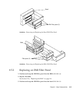
4. Replace the PCI fan assembly.
See Section 8.2.2, “Replacing the PCI Fan Assembly” on page 8-6.
5. Connect the AC power cord.
6. Detach the wrist strap.
7. Replace the side access cover.
See Section 7.3, “Replacing the Side Access Cover” on page 7-4.
8. Power on the system unit.
See Section 6.1, “Powering On the System Unit” on page 6-2.
8.8 DC Switch Assembly
To remove and replace the DC switch assembly, proceed as follows.
8.8.1 Removing the DC Switch Assembly
Caution – Use proper ESD grounding techniques when handling components. Wear
an antistatic wrist strap and use an ESD-protected mat. Store ESD-sensitive
components in antistatic bags before placing them on any surface.
Caution – The DC switch assembly removal procedure is a complex procedure. It is
recommended that a qualified field service representative perform this procedure.
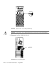
1. Power off the system unit.
See Section 6.2, “Powering Off the System Unit” on page 6-3.
Caution – Pressing the front panel power switch does not remove all power from
the system unit; a trickle voltage remains in the power supply. To remove all power
from the system unit, disconnect the AC power cord.


