Chapter 10 Motherboard and Component Replacement 10-25
3. Replace the motherboard as follows:
a. Replace the following to the motherboard:
■ NVRAM/TOD with carrier. See Section 10.2.2, “Replacing the NVRAM/TOD”
on page 10-6.
■ DIMMs. See Section 10.5.2, “Replacing a DIMM” on page 10-15.
■ Shroud assembly. See Section 8.10.2, “Replacing the Shroud Assembly” on
page 8-39.
■ CPU modules. See Section 10.1.3, “Replacing the CPU Module” on page 10-4.
b. Grasping the shroud assembly handle, position the motherboard into the
chassis.
c. Using a number 2 Phillips-head screwdriver, proceed as follows:
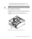
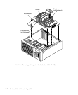
■ Tighten the two captive screws securing the shroud assembly and the
motherboard to the chassis (
FIGURE 10-8).
■ Replace the three screws securing the motherboard to the chassis (FIGURE 10-7).
d. Connect the following:
■ Peripheral cable. See Section 8.4.2, “Replacing the Peripheral Power Cable
Assembly” on page 8-12.
Note – Ensure that the peripheral power cable is routed through the cable routing
clips.
■ External cables.
■ DC power cable.
■ Internal SCSI cable assembly.
Note – Ensure that the SCSI cable is routed through both plastic spring clips
installed adjacent to the drive bay.
■ PCI fan assembly power connector.
e. Latch the shroud to the PCI fan bracket hinge clip.
f. Replace the following to the motherboard:
■ PCI card(s). See Section 10.3.2, “Replacing a PCI Card” on page 10-9.
■ UPA graphics card(s). See Section 10.4.2, “Replacing the UPA Graphics Card”
on page 10-11.
■ Audio card. See Section 10.6.2, “Replacing the Audio Card” on page 10-18.
4. Replace the power supply.
See Section 8.1.2, “Replacing the Power Supply” on page 8-3.


