Chapter 10 Motherboard and Component Replacement 10-5
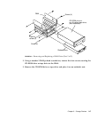
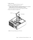
c. Lower the CPU module along the vertical plastic guides until the module
touches the motherboard slot socket. Lock the CPU module in place as follows:
i. With both hands, simultaneously turn and press the levers down to the fully
horizontal position.
ii. Firmly press the module down into the socket until it is fully seated and the
levers are fully locked.
2. Connect the AC power cord.
3. Detach the wrist strap.
4. Replace the side access cover.
See Section 7.3, “Replacing the Side Access Cover” on page 7-4.
5. Power on the system unit.
See Section 6.1, “Powering On the System Unit” on page 6-2.
10.2 NVRAM/TOD
To remove and replace the NVRAM/TOD, proceed as follows.
10.2.1 Removing the NVRAM/TOD
1. Power off the system unit.
See Section 6.2, “Powering Off the System Unit” on page 6-3.
2. Remove the side access cover.
See Section 7.1, “Removing the Side Access Cover” on page 7-2.
Caution – Use proper ESD grounding techniques when handling components. Wear
an antistatic wrist strap and use an ESD-protected mat. Store ESD-sensitive
components in antistatic bags before placing them on any surface.
3. Attach a wrist strap.
See Section 7.2, “Attaching the Wrist Strap” on page 7-3.
4. Remove the power supply.
See Section 8.1.1, “Removing the Power Supply” on page 8-2.


