Appendix C Functional Description C-27
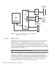
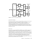
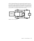
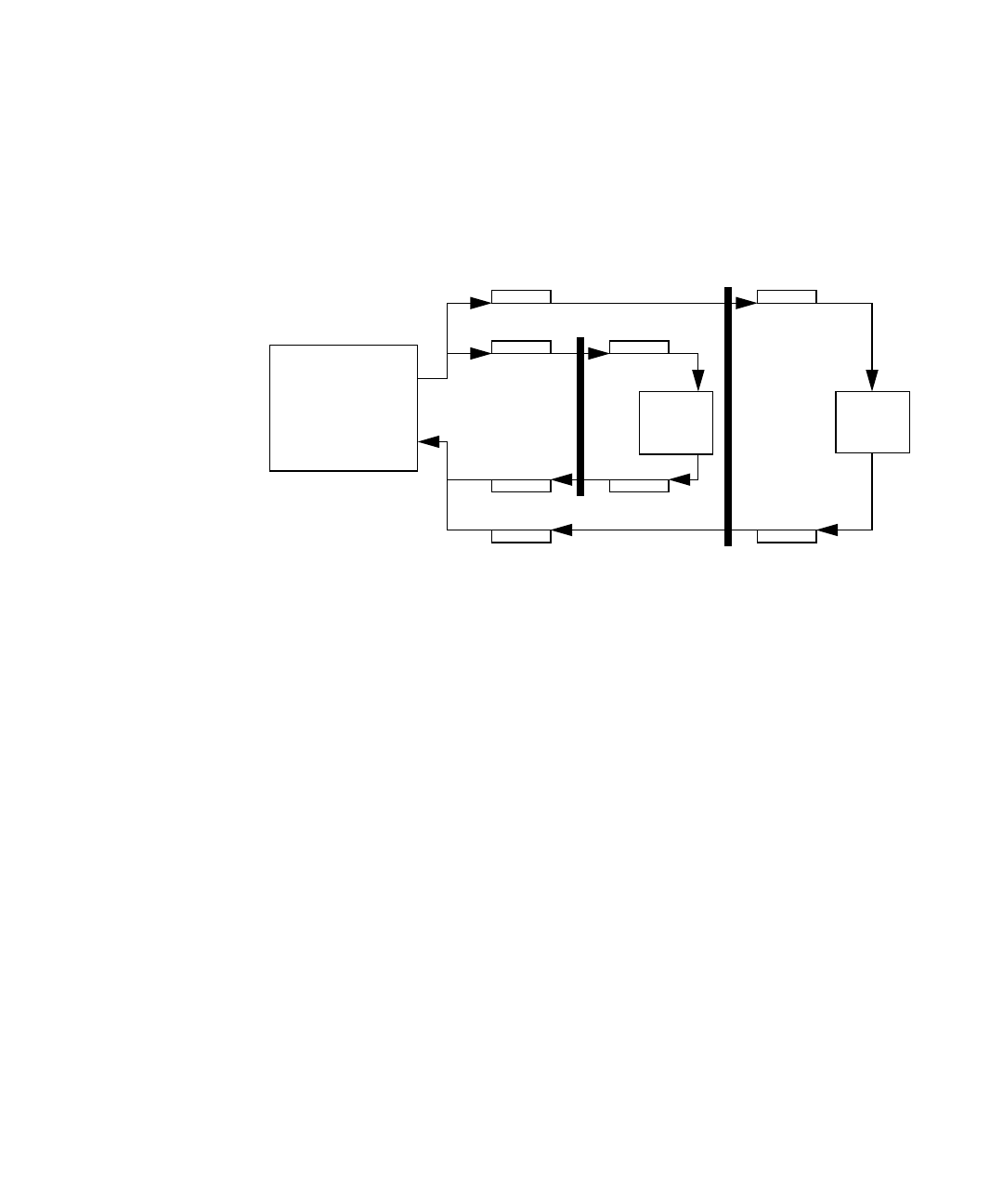
FIGURE C-8 illustrates MII being used to interconnect both integrated circuits and
circuit assemblies. This enables separate signal transmission paths to exist between
the reconciliation sublayer, embedded in the Cheerio ASIC, and a local PHY IC, and
between the reconciliation sublayer and a remote PHY IC. The unidirectional paths
between the reconciliation sublayer and the local PHY IC are composed of sections
A1, B1, C1 and D1. The unidirectional paths between the reconciliation sublayer and
the remote PHY IC are composed of sections A2, B2, C2, and D2.
FIGURE C-8 MII Port Timing Model
PHY
PHY
A1
A2
D1
D2
B1
C1
B2
C2
(local)
(remote)
Reconciliation
sublayer
(Cheerio ASIC)


