Appendix C Functional Description C-37
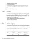
Note – The combined power of output 1 and output 3 must be less than 300 watts.
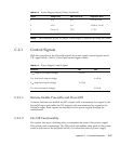
C.2.1 Control Signals
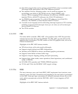
With the exception of the PowerOn signal, all power supply control signals are at
TTL signal levels.
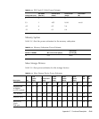
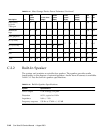
TABLE C-9 lists these control signal values.
C.2.1.1 Remote Enable PowerOn and PowerOff
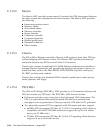
A remote interface can disable the DC outputs with a momentary low signal to the
PowerOff input and enable the DC outputs with a momentary low signal to the
PowerOn input. Both signals are interfaced to the power supply through the
motherboard.
C.2.1.2 On/Off Functionality
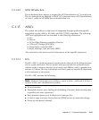
The system unit uses a latching relay to remember the state of the power supply.
This system uses a momentary On/Off switch and enables other parts of the system
(such as software or the keyboard switch) to control the state of power supply.
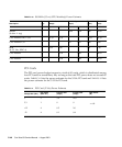
3 12.0 6.0 11.65 to 12.60
4 -12.0 0.4 -12.60 to -11.40
5 2.5 to 3.5 25.0 +/- 2%
TABLE C-9 Power Supply Control Signal
Parameter Min Max
V
OH
(high-level output voltage) 2.4 Vdc
V
OL
(low-level output voltage) 0.4 Vdc
V
IH
(high-level input voltage) 2.0 Vdc
V
IL
(low-level input voltage) 0.8 Vdc
TABLE C-8 Power Supply Output Values (Continued)
Output Voltage (Vdc) Max Current (A) Regulation Band


