


38
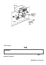
should be chosen by a qualified install er based on the internal vehicle bracket
whic h will be used in s ec uring the sc anner chas s is .
Once the original r adio is removed from the vehicle dash and the fit of the scanner
i s corr ect, be sure to connect all the power, audio, antenna, and any other cables
or wi res, to the scanner before the scanner is secured.
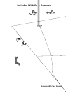
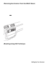
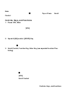
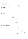
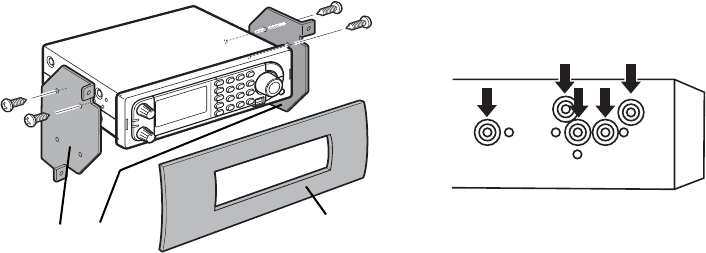
The following illustrat ion is a typica l exa mple of the IS O t echn ique and the general
si de mounting scr ew hol es often encountered. It does not actually represent the
U niden scanner nor your vehicle’s mounting bracket. Only a professional installer
will be able to determine the bes t and c orrect approac h.
Removing the Display Sticker
Be fore you use the sca nn er fo r the first time, re mo ve the pr otective plastic film
over the display.
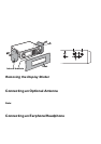
Connecting an Optional Antenna
T he scanner’s BNC connector makes it easy to connect a variety of optional
antennas, including an external mobile antenna or outdoor base station antenna.
Note: Alw a y s use 50 - or 75 - ohm , RG-58, or R G- 8, BN C ter m inat ed c oa xial c ab le
to c on nect an ou tdoo r an ten na. If the antenn a i s o v er 50 feet fr om the sca nner , u s e
RG-8 low-loss dielectric co axia l ca ble. Cab le lo ss in crea ses with higher freq ue ncy.
Connecting an Earphone/Headphone
For pr iv ate listening, you can pl ug a
1
/8-inch (3.5 mm) mini-plug earphone or
headphones (not supplied) i nto the headphone jack on the front of your scanner.
Thi s automatical ly dis connec ts the i nternal speaker. See “Earphone War ning” at
Dash
Internal brackets