


122 AMD Geode™ SC1200/SC1201 Processor Data Book
SuperI/O Module
32579B
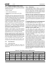
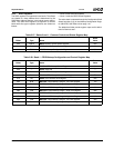
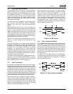
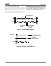
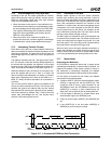
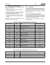
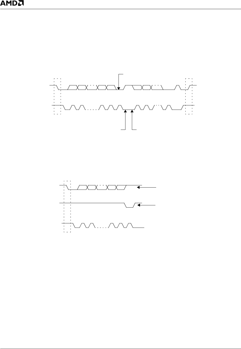
5.7.3 Acknowledge (ACK) Cycle
The ACK cycle consists of two signals: the ACK clock
pulse sent by the master with each byte transferred, and
the ACK signal sent by the receiving device (see Figure 5-
15).
The master generates the ACK clock pulse on the ninth
clock pulse of the byte transfer. The transmitter releases
the ABD line (permits it to go high) to allow the receiver to
send the ACK signal. The receiver must pull down the ABD
line during the ACK clock pulse, signalling that it has cor-
rectly received the last data byte and is ready to receive
the next byte. Figure 5-16 illustrates the ACK cycle.
Figure 5-15. ACCESS.bus Data Transaction
Figure 5-16. ACCESS.bus Acknowledge Cycle
S
P
Start
Condition
Stop
Condition
ABD
ABC
MSB
ACK
ACK
12
3 - 6
7
8
9
1
23 - 8
9
Acknowledge
Signal From Receiver
Byte Complete
Interrupt Within
Receiver
Clock Line Held
Low by Receiver
While Interrupt
is Serviced
S
Start
Condition
ABC
12
3 - 6
7
8
9
Transmitter Stays Off Bus
During Acknowledge Clock
Acknowledge
Signal From Receiver
Data Output
by Transmitter
Data Output
by Receiver