


54 AMD Geode™ SC1200/SC1201 Processor Data Book
Signal Definitions
32579B
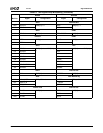
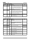
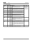
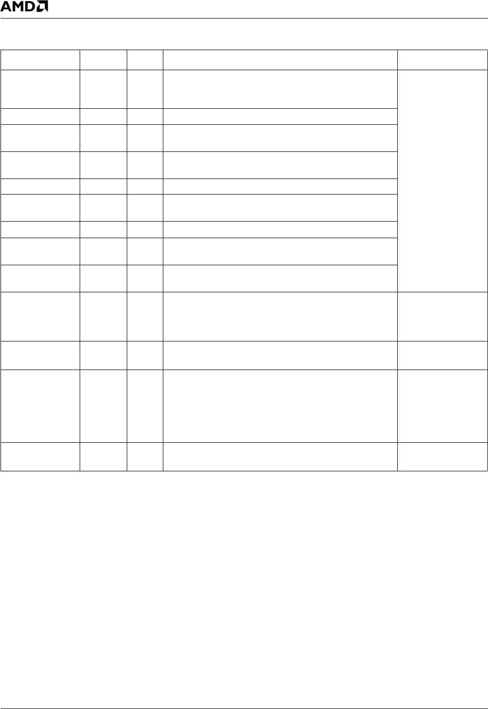
3.4.5 TV Interface Signals
Signal Name Ball No. Type Description Mux
CVBS A23,
A24,
D24
O Composite Video. Includes synchronization, luminance
and chrominance components of video.
See F4BAR0+
Memory Offset
C08h[4:3] bit
description on
page 356 for config-
uration details.
SVY A24 O Super Video Luminance. S-Video luminance signal.
SVC C23 O Super Video Chrominance. S-Video chrominance sig-
nal.
TVR A24,
C23
O TV Red. TV Red component signal for SCART.
TVG A23 O TV Green. TV Green component signal for SCART.
TVB C23,
D24
O TV Blue. TV Blue component signal for SCART.
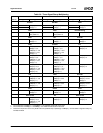
YA23OIntensity. Color intensity vector.
Cr C23,
D24
O Chrominance Red. Red axis phase angle.
Cb A24,
C23
O Chrominance Blue. Blue axis phase angle.
TVREF C24 I/O Voltage Reference. Reference voltage for TV DAC. This
signal reflects the internal voltage reference. If an exter-
nal voltage reference is used, this input is tied to a
1.235V reference.
---
TVCOMP B26 I Current Compensation for TV DAC. A 0.1 µF to 1.2 µF
capacitor is used to connect this ball to AV
CCTV
.
---
TVRSET A25 I TV Set Resistor. This signal sets the current-level for the
TV DAC. Typically, an 1140 Ω, 1% resistor is connected
between this ball and AV
SSTV
. The full scale current out-
put of TV DACs is 32 * TVREF / TVRSET. An 1140 Ω, 1%
resistor enables driving a double terminated 75 Ω trans-
mission line.
---
TVIOM B23 O TV Output Dump Current. Typically, a 9.3 Ω, 1% resistor
is connected between this ball and AV
SSTV
.
---