


AMD Geode™ SC1200/SC1201 Processor Data Book 79
General Configuration Block
32579B
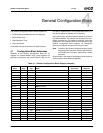
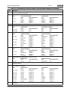
4.3 WATCHDOG
The SC1200/SC1201 processor includes a WATCHDOG
function to serve as a fail-safe mechanism in case the sys-
tem becomes hung. When triggered, the WATCHDOG
mechanism returns the system to a known state by gener-
ating an interrupt, an SMI, or a system reset (depending on
configuration).
4.3.1 Functional Description
WATCHDOG is enabled when the WATCHDOG Timeout
(WDTO) register (Offset 00h) is set to a non-zero value.
The WATCHDOG timer starts with this value and counts
down until either the count reaches 0, or a trigger event
restarts the count (with the WDTO register value).
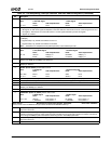
The WATCHDOG timer is restarted in any of the following
cases:
• The WDTO register is set with a non-zero value.
• The WATCHDOG timer reaches 0 and the WATCHDOG
Overflow bit, WDOVF (Offset 04h[0]), is 0.
The WATCHDOG function is disabled in any of the follow-
ing cases:
• System reset occurs.
• The WDTO register is set to 0.
• The WDOVF bit is already 1 when the timer reaches 0.
4.3.1.1 WATCHDOG Timer
The WATCHDOG timer is a 16-bit down counter. Its input
clock is a 32 KHz clock divided by a predefined value (see
WDPRES field, Offset 02h[3:0]). The 32 KHz input clock is
enabled when either:
• The GX1 module’s internal SUSPA# signal is 1.
or
• The GX1 module’s internal SUSPA# signal is 0 and the
WD32KPD bit (Offset 02h[8]) is 0.
The 32 KHz input clock is disabled, when:
• The GX1 module’s internal SUSPA# signal is 0 and the
WD32KPD bit is 1.
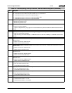
For more information about signal SUSPA#, refer to the
AMD Geode™ GX1 Processor Data Book.
When the WATCHDOG timer reaches 0:
• If the WDOVF bit in the WDSTS register (Offset 04h[0])
is 0, an interrupt, an SMI or a system reset is generated,
depending on the value of the WDTYPE1 field in the
WDCNFG register (Offset 02h[5:4]).
• If the WDOVF bit in the WDSTS register is already 1
when the WATCHDOG timer reaches 0, an interrupt, an
SMI or a system reset is generated according to the
WDTYPE2 field (Offset 02h[7:6]), and the timer is
disabled. The WATCHDOG timer is re-enabled when a
non-zero value is written to the WDTO register (Offset
00h).
The interrupt or SMI is de-asserted when the WDOVF bit is
set to 0. The reset generated by the WATCHDOG function
is used to trigger a system reset via the Core Logic mod-
ule. The value of the WDOVF bit, the WDTYPE1 field, and
the WDTYPE2 field are not affected by a system reset
(except when generated by power-on reset).
The SC1200/SC1201 processor also allows no action to be
taken when the timer reaches 0 (according to WDTYPE1
field and WDTYPE2 field). In this case only the WDOVF bit
is set to 1.
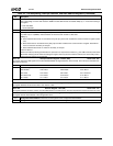
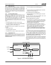
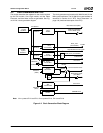
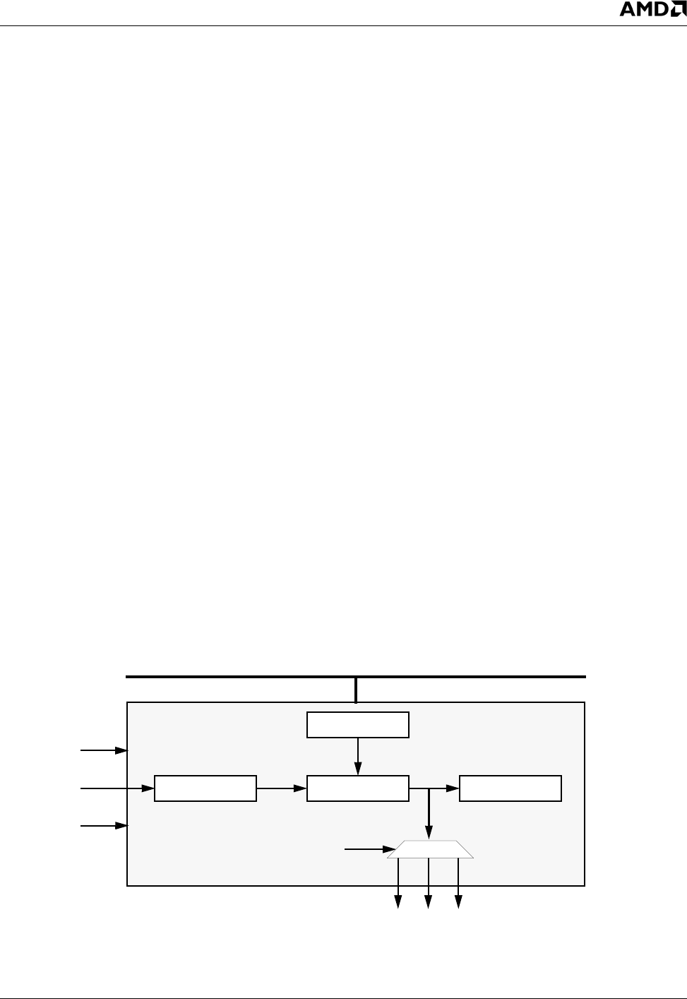
Figure 4-1. WATCHDOG Block Diagram
WDPRES
WDTO
Timer WDOVF
WDTYPE1 or
WDTYPE2
Internal Fast-PCI Bus
32 KHz
POR#
WATCHDOG
Reset IRQ SMI
SUSPA#