


AMD Geode™ SC1200/SC1201 Processor Data Book 159
Core Logic Module
32579B
6.2.9.2 Sleep States
The SC1200/SC1201 processor supports four Sleep states
(SL1-SL3) and the Soft Off state (G2/S5). These states are
fully compliant with the ACPI specification, revision 1.0.
When the SLP_EN bit (F1BAR1+I/O Offset 0Ch[13]) is set
to 1, the SC1200/SC1201 processor enters an SLx state
according to the SLP_TYPx field (F1BAR1+I/O Offset
0Ch[12:10]). It exits the Sleep state back to the S0 state
(C0 state - Full Speed or Throttling, depending on the
THT_EN bit) upon an enabled power management event.
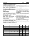
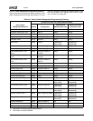
Table 6-5 on page 159 lists wakeup events from the various
Sleep states.
SL1 Sleep State (ACPI S1)
In this state the core processor is in 3V Suspend mode (all
its clocks are stopped, including the memory controller and
the display controller). The SDRAM is placed in self-refresh
mode. All other SC1200/SC1201 processor system clocks
and PLLs are running. All devices are powered up
(PWRCNT[2:1] and ONCTL# are all asserted). See Sec-
tion 6.2.9.5 "Usage Hints" on page 161.
No reset is performed, when exiting this state. The
SC1200/SC1201 processor keeps all context in this state.
This state corresponds to ACPI Sleep state S1.
SL2 Sleep State (ACPI S1)
In this state, all of the SC1200/SC1201 processor clocks
are stopped including the PLLs. Selected clocks from the
PLLs can be kept running under program control (F0 Index
60h). An exception to this is the CLK32 output signal which
keeps toggling and the 32 KHz oscillator itself. The
SDRAM is placed in self-refresh mode. The PWRCNT1 pin
is de-asserted. The SC1200/SC1201 processor itself is
powered up. The system designer can decide which other
system devices to power off with the PWRCNT1 pin.
No reset is performed, when exiting this state. The
SC1200/SC1201 processor keeps all context in this state.
This state corresponds to ACPI sleep state S1, with lower
power and longer wake time than in SL1.
SL3 Sleep State (ACPI S3)
In this state, the SDRAM is placed in self-refresh mode,
and PWRCNT[2:1] are de-asserted. PWRCNT[2:1] should
be used to power off most of the system (except for the
SDRAM). If the Save-to-RAM feature is used, external cir-
cuitry in the SDRAM interface is required to guarantee data
integrity. All SC1200/SC1201 processor signals powered
by V
SB
, V
SBL
or V
BAT
are still functional to allow wakeup
and to keep the RTC.
The power-up sequence is performed, when exiting this
state. This state corresponds to ACPI Sleep state S3.
SL4 and SL5 Sleep States (ACPI S4 and S5)
The SL4 and SL5 states are similar from the hardware per-
spective. In these states, the SC1200/SC1201 processor
de-asserts PWRCNT[2:1] and ONCTL#. PWRCNT[2:1]
and ONCTL# should be used to power off the system. All
signals powered by V
SB
, V
SBL
or V
BAT
are still functional to
allow wakeup and to keep the RTC.
While in this state, LED# can be toggled to give visual noti-
fication of this state. ACPI Function Control register
(F1BAR1+I/O Offset 07h[7:6]) is used to control LED#.
The power-up sequence is performed when exiting this
state. This state corresponds to ACPI Sleep states S4 and
S5.
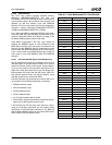
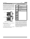
Table 6-5. Wakeup Events Capability
Event S0/C1 S0/C3 SL1 SL2 SL3 SL4, SL5
Enabled Interrupts Yes Yes Yes - - -
SMI according to Table 6-8 Yes Yes Yes - - -
SCI according to Table 6-8 Yes Yes Yes - - -
GPIO[47:32], GPIO[15:0] Yes Yes Yes - - -
Power Button Yes Yes Yes Yes Yes Yes
Power Button Override Yes Yes Yes Yes Yes Yes
Bus Master Request
Ye s
1
YesYes---
Thermal Monitoring Yes Yes Yes Yes Yes Yes
USB Yes Yes Yes Yes - -
SDATA_IN2 (AC97) Yes Yes Yes Yes - -
IRRX1 (Infrared) Yes Yes Yes Yes - -
GPWIO[2:0] Yes Yes Yes Yes Yes Yes
RI2# (UART2) Yes Yes Yes Yes - -
RTC Yes Yes Yes Yes Yes Yes
1. Temporarily exits state.