


64 AMD Geode™ SC1200/SC1201 Processor Data Book
Signal Definitions
32579B
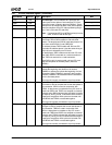
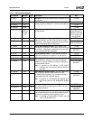
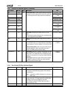
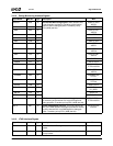
PD7 A18 I/O Parallel Port Data. Transfer data to and from the periph-
eral data bus and the appropriate Parallel Port data regis-
ter. These signals have a high current drive capability.
TFTD13+F_AD7
PD6 A20 TFTD1+VOPD0+
F_AD6
PD5 C19 TFTD11+F_AD5
PD4 C18 TFTD10+F_AD4
PD3 C20 TFTD9+F_AD3
PD2 D20 TFTD8+VOPD7+
F_AD2
PD1 A21 TFTD7+VOPD6+
F_AD1
PD0 C21 TFTD6+VOPD5+
F_AD0
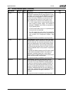
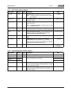
PE D17 I Paper End. Set high by the printer when it is out of
paper.
This ball has an internal weak pull-up or pull-down resis-
tor that is programmed by software.
TFTD14+F_C/BE2#
SLCT C17 I Select. Set active high by the printer when the printer is
selected.
TFTD15+F_C/BE3#
SLIN#/ASTRB# B20 O Select Input. When low, selects the printer. This signal
is in TRI-STATE after a 0 is loaded into the corresponding
control register bit. Uses an external 4.7 KΩ pull-up resis-
tor.
Address Strobe (EPP). Active low, used in EPP mode to
denote an address or data cycle. When the cycle is
aborted, ASTRB# becomes inactive (high).
TFTD16+
F_IRDY#
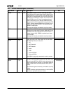
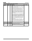
STB#/WRITE# A22 O Data Strobe. When low, indicates to the printer that valid
data is available at the printer port. This signal is in TRI-
STATE after a 0 is loaded into the corresponding control
register bit. An external 4.7 KΩ pull-up resistor should be
employed.
Write Strobe. Active low, used in EPP mode to denote
an address or data cycle. When the cycle is aborted,
WRITE# becomes inactive (high).
TFTD17+
F_FRAME#
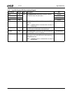
3.4.13 Parallel Port Interface Signals (Continued)
Signal Name Ball No. Type Description Mux
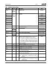
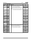
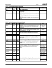
3.4.14 Fast Infrared (IR) Port Interface Signals
Signal Name Ball No. Type Description Mux
IRRX1 AK8 I IR Receive. Primary input to receive serial data from the
IR transceiver. Monitored during power-off for wakeup
event detection.
Note: If selected as IRRX1 function but not used, tie
IRRX1 high.
SIN3
IRRX2/GPIO38 K28 I IR Receive 2. Auxiliary IR receiver input to support a
second transceiver. This input signal can be used when
GPIO38 is selected using PMR[14], and when
AUX_IRRX bit in register IRCR2 of the IR module in
internal SuperI/O is set.
LPCPD#
IRTX C11 O IR Transmit. IR serial output data. SOUT3