


366 AMD Geode™ SC1200/SC1201 Processor Data Book
Electrical Specifications
32579B
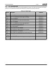
9.1.4 Operating Conditions
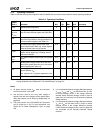
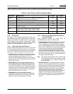
Table 9-3 lists the various power supplies of the SC1200/SC1201 processor and provides the device operating conditions.
Notes:
1) All power sources except V
BAT
must be connected,
even if the function is not used.
2) V
SB
and V
SBL
must be on if any other voltage is
applied. V
SB
and V
BAT
voltages can be applied sepa-
rately. See Section 9.3.16 "Power-Up Sequencing" on
page 433.
3) The power planes of the SC1200/SC1201 processor
can be turned on or off. For more information, see
Section 6.2.9 "Power Management Logic" on page
158.
4) It is recommended that the voltage difference between
V
CCCRT
, V
CORE
and V
SBL
be less than 0.25V, in order
to reduce leakage current. If the voltage difference
exceeds 0.25V, excessive leakage current is used in
gates that are connected on the boundary between
voltage domains.
5) It is recommended that the voltage difference between
V
IO
and V
SB
be less than 0.25V, in order to reduce
leakage current. If the voltage difference exceeds
0.25V, excessive leakage current is used in gates that
are connected on the boundary between voltage
domains.
Table 9-3. Operating Conditions
Symbol
(Note 1)
Note 1. For V
IH
(Input High Voltage), V
IL
(Input Low Voltage), I
OH
(Output High Current), and I
OL
(Output Low Current) op-
erating conditions refer to Section 9.2 "DC Characteristics" on page 371.
Parameter Min Typ Max Unit Comments
T
CASE
Operating case temperature 0 - 85
o
C
AV
CCUSB
AV
CCCRT
AV
CCTV
Analog power supply. Powers internal analog cir-
cuits and some external signals (see Table 9-4).
3.14 3.3 3.46 V
V
BAT
Battery supply voltage. Powers RTC and ACPI
when V
BAT
is greater than V
SB
(by at least 0.5V),
and some external signals (see Table 9-4).
2.4 3.0 3.46 V
V
IO
I/O buffer power supply. Powers most of the
external signals (see Table 9-4); certain signals
within this power plane are 5V tolerant.
3.14 3.3 3.46 V
V
CORE
Core processor and internal digital power supply.
Powers internal digital logic, including internal
frequency multipliers.
1.71 1.8 2.1 V
V
PLL2
V
PLL3
PLL. Internal Phase Locked Loops (PLLs) power
supply.
3.14 3.3 3.46 V
V
SB
Standby power supply. Powers RTC and ACPI
when V
SB
is greater than V
BAT
-0.5V, and some
external signals (see Table 9-4).
3.14 3.3 3.46 V
V
SBL
Standby logic. Powers internal logic needed to
support Standby V
SB
.
V
SBL
requires a 0.1 µF bypass capacitor to V
SS
.
1.71 1.8 2.1 V
V
CCCRT
CRT DAC. Powers CRT DAC digital circuits. 1.71 1.8 2.1 V