336 AMD Geode™ SC1200/SC1201 Processor Data Book
Video Processor Module - Video Processor Registers - Function 4
32579B
7.3.2 Video Processor Registers - Function 4
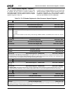
The register space designated as Function 4 (F4) is used
to configure the PCI portion of support hardware for
accessing the Video Processor support registers, including
VIP (separate BAR). The bit formats for the PCI Header
registers are given in Table 7-8.
Located in the PCI Header Registers of F4 are three Base
Address Registers (F4BARx) used for pointing to the regis-
ter spaces designated for Video Processor support.
F4BAR0 is for Video Processor Configuration, F4BAR1 is
reserved, and F4BAR2 is for VIP configuration.
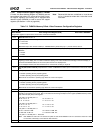
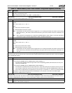
Table 7-8. F4: PCI Header Registers for Video Processor Support Registers
Bit Description
Index 00h-01h Vendor Identification Register (RO) Reset Value: 100Bh
Index 02h-03h Device Identification Register (RO) Reset Value: 0504h
Index 04h-05h PCI Command Register (R/W) Reset Value: 0000h
15:2 Reserved. (Read Only)
1 Memory Space. Allow the Core Logic module to respond to memory cycles from the PCI bus.
0: Disable.
1: Enable.
This bit must be enabled to access memory offsets through F4BAR0, F4BAR1, and F4BAR2 (see F4 Index 10h, 14h, and
18h).
0 Reserved. (Read Only)
Index 06h-07h PCI Status Register (RO) Reset Value: 0280h
Index 08h Device Revision ID Register (RO) Reset Value: 01h
Index 09h-0Bh PCI Class Code Register (RO) Reset Value: 030000h
Index 0Ch PCI Cache Line Size Register (RO) Reset Value: 00h
Index 0Dh PCI Latency Timer Register (RO) Reset Value: 00h
Index 0Eh PCI Header Type (RO) Reset Value: 00h
Index 0Fh PCI BIST Register (RO) Reset Value: 00h
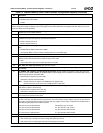
Index 10h-13h Base Address Register 0 - F4BAR0 (R/W) Reset Value: 00000000h
Video Processor Video Memory Address Space. This register allows PCI access to the memory mapped Video Processor configura-
tion registers. Bits [11:0] are read only (0000 0000 0000) indicating a 4 KB memory address range. See Table 7-9 on page 338 for bit for-
mats and reset values of the registers accessed through this base address register.
31:12 Video Processor Video Memory Base Address.
11:0 Address Range. (Read Only)
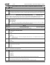
Index 14h-17h Base Address Register 1 - F4BAR1 (R/W) Reset Value: 00000000h
Reserved.
Index 18h-1Bh Base Address Register 2 - F4BAR2 (R/W) Reset Value: 00000000h
VIP Address Space. This register allows access to memory mapped VIP (Video Interface Port) related registers. Bits [11:0] are read
only (0000 0000 0000), indicating a 4 KB I/O address range. Refer to Table 7-10 for the VIP register bit formats and reset values.
31:12 VIP Base Address.
11:0 Address Range. (Read Only)
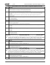
Index 1Ch-2Bh Reserved Reset Value: 00h
Index 2Ch-2Dh Subsystem Vendor ID (RO) Reset Value: 100Bh
Index 2Eh-2Fh Subsystem ID (RO) Reset Value: 0504h
Index 30h-3Bh Reserved Reset Value: 00h
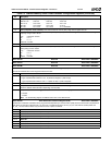
Index 3Ch Interrupt Line Register (R/W) Reset Value: 00h
This register identifies the system interrupt controllers to which the device’s interrupt pin is connected. The value of this register is used
by device drivers and has no direct meaning to this function.


