


AMD Geode™ SC1200/SC1201 Processor Data Book 319
Video Processor Module
32579B
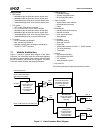
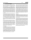
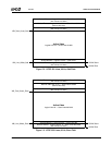
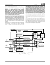
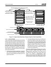
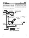
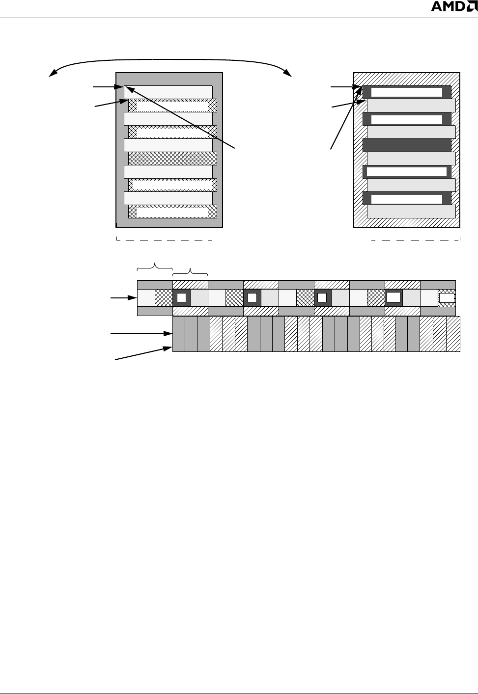
Figure 7-6. Capture Video Mode Weave Example Using Two Video Frame Buffers
7.2.1.4 Capture VBI Mode
There are three types of VBI data defined by the CCIR-656
protocol: Task A data, Task B data, and Ancillary data. The
VIP block supports the capture for each data type. Gener-
ally Task A data is the data type captured. Just as in Cap-
ture Video mode, there are three registers that tell the bus
master where to put the raw VBI data in the GX1 module’s
frame buffer. Once the raw VBI data has been captured,
the data can be manipulated or decoded. The VIP block
has two options of what to do with the altered VBI data.
These options are independent functions so both options
can be done simultaneously.
1) The data can be used by an application. An example
of this would be an Internet address that is encoded on
one or more of the VBI lines, or have an application
decode the Closed Captioning information put in the
graphics frame buffer.
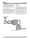
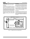
2) The altered VBI data can be sent to the TVOUT block
of the Video Processor via the video frame buffer or
graphics frame buffer. See VIP block diagram (Figure
7-4 on page 315). The Closed Captioning data could
be altered and then sent out this way. One reason to
capture the Closed Captioning data would be to do a
language conversion. If the VIP block is in Capture
Video mode then this option is not possible because
the video frame buffer can be used for sending video
or VBI, but not simultaneously.
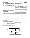
The registers, F4BAR2+Memory Offset 40h, 44h, and 48h,
tell the bus master the destination addresses for the VBI
data in the GX1 module’s frame buffer. Five bits
(F4BAR2+Memory Offset 00h[21:17]) are used to tell the
bus master the data types to store. Capture VBI mode
needs to be enabled at F4BAR2+Memory Offset
04h[9,1:0]. The Field Interrupt bit (F4BAR2+Memory Offset
04h[16]) should be used by the software driver to know
when the captured VBI data has been completed for a field.
Video Data Odd Base
F
4BAR2+Memory Offset 20h
Video Data Even Base
F4BAR2+Memory Offset 20h
VID_START_OFFSET
GX_BASE+Memory Offset 8320h
Ping-pongs between the
two buffers during runtime
GX1 Module’s Video Frame Buffer
12 4567891011121314151617
1234 67891011121314151617181920 22
Capture video fill sequence
GX1 Module’s Display
5
5
21
Video Data Even Base
F
4BAR2+Memory Offset 24h
Video Data Even Base
F4BAR2+Memory Offset 24h
Odd and Even fields are
Buf #2
Video Frame Buffer #1 Video Frame Buffer #2
18
235
11
3
7
Line 1 Odd Field
Line n Odd Field
Line 2 Odd Field
Line 1 Even Field
Line 2 Even Field
Line n-1 Odd Field
Line n-1 Even Field
Line n Odd Field
Line n Even Field
Line 1 Odd Field
Line 1 Even Field
Line 2 Odd Field
Line 2 Even Field
Line n-1 Odd Field
Line n-1 Even Field
Line n Even Field
15
18
85 frames per second
30 frames per second
Buf #1
Controller empty sequence
“Weaved” together
Ping-pongs between the two buffers during runtime