302 AMD Geode™ SC1200/SC1201 Processor Data Book
Core Logic Module - ISA Legacy Register Space
32579B
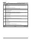
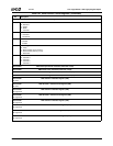
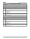
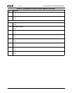
Table 6-45. Programmable Interval Timer Registers
Bit Description
I/O Port 040h
Write PIT Timer 0 Counter
7:0 Counter Value.
Read PIT Timer 0 Status
7 Counter Output. State of counter output signal.
6 Counter Loaded. Indicates if the last count written is loaded.
0: Yes.
1: No.
5:4 Current Read/Write Mode.
00: Counter latch command.
01: R/W LSB only.
10: R/W MSB only.
11: R/W LSB, followed by MSB.
3:1 Current Counter Mode. 0-5.
0 BCD Mode.
0: Binary.
1: BCD (Binary Coded Decimal).
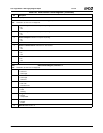
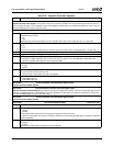
I/O Port 041h
Write PIT Timer 1 Counter (Refresh)
7:0 Counter Value.
Read PIT Timer 1 Status (Refresh)
7 Counter Output. State of counter output signal.
6 Counter Loaded. Indicates if the last count written is loaded.
0: Yes.
1: No.
5:4 Current Read/Write Mode.
00: Counter latch command.
01: R/W LSB only.
10: R/W MSB only.
11: R/W LSB, followed by MSB.
3:1 Current Counter Mode. 0-5.
0 BCD Mode.
0: Binary.
1: BCD (Binary Coded Decimal).


