AMD Geode™ SC1200/SC1201 Processor Data Book 295
Core Logic Module - USB Controller Registers - PCIUSB
32579B
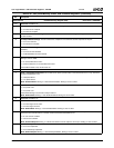
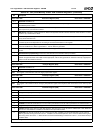
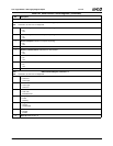
Offset 100h-103h HceControl Register (R/W) Reset Value = 00000000h
31:9 Reserved. Read/Write 0s.
8 A20State. Indicates current state of Gate A20 on keyboard controller. Compared against value written to 60h when
GateA20Sequence is active.
7 IRQ12Active. Indicates a positive transition on IRQ12 from keyboard controller occurred. Software writes this bit to 1 to
clear it (set it to 0); a 0 write has no effect.
6 IRQ1Active. Indicates a positive transition on IRQ1 from keyboard controller occurred. Software writes this bit to 1 to clear
it (set it to 0); a 0 write has no effect.
5 GateA20Sequence. Set by HC when a data value of D1h is written to I/O port 64h. Cleared by HC on write to I/O port 64h
of any value other than D1h.
4 ExternalIRQEn. When set to 1, IRQ1 and IRQ12 from the keyboard controller cause an emulation interrupt. The function
controlled by this bit is independent of the setting of the EmulationEnable bit in this register.
3 IRQEn. When set, the HC generates IRQ1 or IRQ12 as long as the OutputFull bit in HceStatus is set to 1. If the AuxOutput-
Full bit of HceStatus is 0, IRQ1 is generated: if 1, then an IRQ12 is generated.
2 CharacterPending. When set, an emulation interrupt will be generated when the OutputFull bit of the HceStatus register is
set to 0.
1 EmulationInterrupt (Read Only). This bit is a static decode of the emulation interrupt condition.
0 EmulationEnable. When set to 1 the HC is enabled for legacy emulation and will decode accesses to I/O registers 60h
and 64h and generate IRQ1 and/or IRQ12 when appropriate. The HC also generates an emulation interrupt at appropriate
times to invoke the emulation software.
Note: This register is used to enable and control the emulation hardware and report various status information.
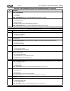
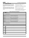
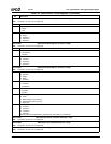
Offset 104h-107h HceInput Register (R/W) Reset Value = 000000xxh
31:8 Reserved. Read/Write 0s.
7:0 InputData. This register holds data written to I/O ports 60h and 64h.
Note: This register is the emulation side of the legacy Input Buffer register.
Offset 108h-10Bh HceOutput Register (R/W) Reset Value = 000000xxh
31:8 Reserved. Read/Write 0s.
7:0 OutputData. This register hosts data that is returned when an I/O read of port 60h is performed by application software.
Note: This register is the emulation side of the legacy Output Buffer register where keyboard and mouse data is to be written by soft-
ware.
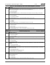
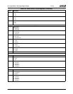
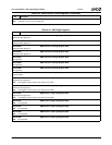
Offset 10Ch-10Fh HceStatus Register (R/W) Reset Value = 00000000h
31:8 Reserved. Read/Write 0s.
7 Parity. Indicates parity error on keyboard/mouse data.
6 Timeout. Used to indicate a time-out
5 AuxOutputFull. IRQ12 is asserted whenever this bit is set to 1 and OutputFull is set to 1 and the IRQEn bit is set.
4 Inhibit Switch. This bit reflects the state of the keyboard inhibit switch and is set if the keyboard is NOT inhibited.
3 CmdData. The HC will set this bit to 0 on an I/O write to port 60h and on an I/O write to port 64h the HC will set this bit to 1.
2 Flag. Nominally used as a system flag by software to indicate a warm or cold boot.
1 InputFull. Except for the case of a Gate A20 sequence, this bit is set to 1 on an I/O write to address 60h or 64h. While this
bit is set to 1 and emulation is enabled, an emulation interrupt condition exists.
0 OutputFull. The HC will set this bit to 0 on a read of I/O port 60h. If IRQEn is set and AuxOutputFull is set to 0 then an
IRQ1 is generated as long as this bit is set to 1. If IRQEn is set and AuxOutputFull is set to 1 then and IRQ12 will be gener-
ated a long as this bit is set to 1. While this bit is 0 and CharacterPending in HceControl is set to 1, an emulation interrupt
condition exists.
Note: This register is the emulation side of the legacy Status register.
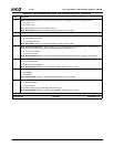
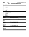
Table 6-42. USB_BAR+Memory Offset: USB Controller Registers (Continued)
Bit Description


