


AMD Geode™ SC1200/SC1201 Processor Data Book 367
Electrical Specifications
32579B
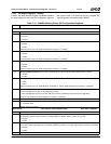
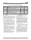
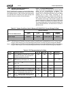
Table 9-4 indicates which power rails are used for each signal of the SC1200/SC1201 processor’s external interface. Power
planes not listed in this table are internal, and are not related to signals of the external interface.
9.1.5 DC Current
DC current is not a simple measurement. Three of the
SC1200/SC1201 processor’s power states (On, Active Idle,
Sleep) were selected for measurement. For each power
state measured, two functional characteristics (Typical
Average, Absolute Maximum) are used to determine how
much current the SC1200/SC1201 processor uses.
9.1.5.1 Power State Parameter Definitions
The DC characteristics tables in this section list Core and
I/O current for three of the power states. For more explana-
tion on the SC1200/SC1201 processor’s power states see
Section 6.2.9 "Power Management Logic" on page 158.
•On (C0): All internal and external clocks with respect to
the SC1200/SC1201 processor are running and all func-
tional blocks inside the GX1 module (CPU Core,
Memory Controller, Display Controller, etc.) are actively
generating cycles. This is equivalent to the ACPI specifi-
cation’s “S0,C0” state.
• Active Idle (C1): The CPU Core has been halted, all
other functional blocks (including the Display Controller
for refreshing the display) are actively generating cycles.
This state is entered when a HLT instruction is executed
by the CPU Core. From a user’s perspective, this state is
indistinguishable from the On state and is equivalent to
the ACPI specification’s “S0,C1” state.
•Sleep (SL2): This is the lowest power state the
SC1200/SC1201 processor can be in with voltage still
applied to the device’s core and I/O supply pins. This is
equivalent to the ACPI specification’s “S1” state.
9.1.5.2 Definition and Measurement Techniques of
Current Parameters
These parameters describe the current while the
SC1200/SC1201 processor is in the On state:
• Typical Average: Indicates the average current used by
the SC1200/SC1201 processor while in the On state.
This is measured by running typical Windows applica-
tions in a typical display mode. In this case, 800x600x8
bpp at 75 Hz, 50 MHz DCLK using a background image
of vertical stripes (4-pixel wide) alternating between
black and white with power management disabled (to
guarantee that the SC1200/SC1201 processor never
goes into the Active Idle state). This number is provided
for reference only since it can vary greatly depending on
the usage model of the system.
Note: This typical average should not be confused with
the typical power numbers. Typical power is based
on a combination of On (Typical Average) and
Active Idle states.
• Absolute Maximum: Indicates the maximum instanta-
neous current used by the SC1200/SC1201 processor.
CPU Core current is measured by running the Landmark
Speed 200
benchmark test (with power management
disabled) and measuring the peak current at any given
instant during the test. I/O current is measured by
running Microsoft Windows 98 and using a background
image of vertical stripes (1-pixel wide) alternating
between black and white at the maximum display resolu-
tion of each of the display type supported (CRT, TFT,
and TV).
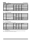
Table 9-4. Power Planes of External Interface Signals
Power Plane Signal Names
V
CC
Balls V
SS
Balls
Standby GPWIO[0:2], LED#, ONCTL#, PWRBTN#, PWRCNT[1:2],
THRM#, CLK32, IRRX1, RI2#, SDATA_IN2
V
SB
V
SS
Battery X32I, X32O V
BAT
V
SS
CRT DAC RED, GREEN, BLUE, VREF, SETRES AV
CCCRT
AV
SSCRT
TV DAC CVBS, SVY, SVC, TVB, TVR, Cr, Cab, Y, TVREF, TVRSET,
TVIOM, TVCOMP
AV
CCTV
AV
SSTV
USB DPOS_PORT1, DNEG_PORT1, DPOS_PORT2,
DNEG_PORT2, DPOS_PORT3, DNEG_PORT3
AV
CCUSB
AV
SSUSB
I/O All other external interface signals V
IO
V
SS