26 AMD Geode™ SC1200/SC1201 Processor Data Book
Signal Definitions
32579B
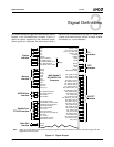
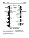
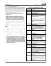
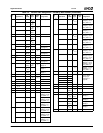
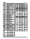
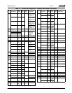
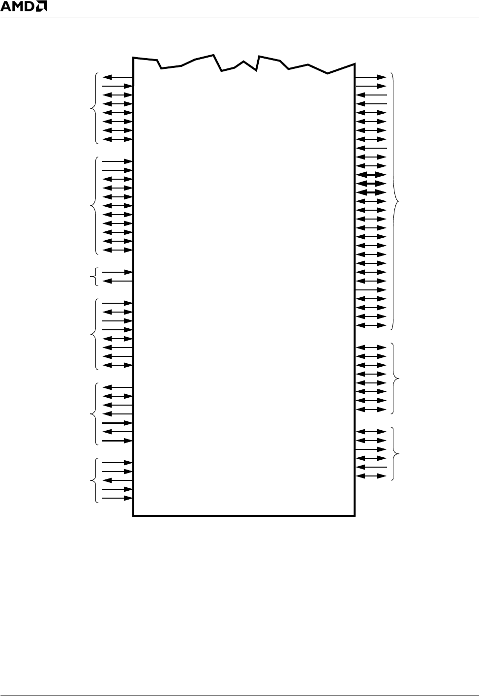
Figure 3-1. Signal Groups (Continued)
The remaining subsections of this chapter describe:
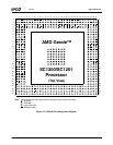
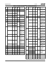
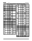
• Section 3.1 "Ball Assignments": Provides a ball assign-
ment diagram and tables listing the signals sorted
according to ball number and alphabetically by signal
name.
• Section 3.2 "Strap Options": Several balls are read at
power-up that set up the state of the SC1200/SC1201
processor. This section provides details regarding those
balls.
• Section 3.3 "Multiplexing Configuration": Lists multi-
plexing options and their configurations.
• Section 3.4 "Signal Descriptions": Detailed descriptions
of each signal according to functional group.
Serial Ports
SIN1
SOUT1+CLKSEL1
GPIO7+RTS2#+IDE_DACK1#+SDTEST0
GPIO8+CTS2#+IDE_DREQ1+SDTEST4
GPIO6+DTR2#/BOUT2+IDE_IOR1#+SDTEST5
AC97 Audio
BIT_CLK
SDATA_OUT+TFT_PRSNT
SDATA_IN
SDATA_IN2
SYNC+CLKSEL3
AC97_CLK
AC97_RST#
GPIO16+PC_BEEP
Power
CLK32
GPWIO[2:0]
LED#
ONCTL#
PWRBTN#
PWRCNT[1:2]
THRM#
TCK
TDI
TDO
TMS
TRST#
JTAG
TEST1+PLL6B
TEST0+PLL2B
TEST3+GXCLK+FP_VDD_ON
TEST2+PLL5B
GTEST
Test and
TDP, TDN
GPIO11+RI2#+IRQ15
GPIO18+DTR1#/BOUT1
GPIO9+DCD2#+IDE_IOW1#+SDTEST2
GPIO10+DSR2#+IDE_IORDY1+SDTEST1
IR Port
IRRX1+SIN3
IRTX+SOUT3
PCICLK
INTA#, INTB#
FRAME#
LOCK#
PERR#
SERR#
REQ[1:0]#
GNT0#+DID0
POWER_EN
OVER_CUR#
DPOS_PORT1
DNEG_PORT1
DPOS_PORT2
DNEG_PORT2
DPOS_PORT3
DNEG_PORT3
USB
A[23:0]/AD[23:0]
D[11:8]/C/BE[3:0]#
BHE#/DEVSEL#
GPIO1+IOCS1+TFTD12
ROMCS#/BOOT16
GPIO20+DOCCS#+TFTD0
RD#+CLKSEL0
WR#
Sub-ISA/PCI Bus
GPIO14+DOCR#+IOR#
GPIO15+DOCW#+IOW#
SOUT2+CLKSEL2
D[7:0]/AD[31:24]
D12/PAR
D13/TRDY#
D14/IRDY#
D15/STOP#
SIN2+SDTEST3
GPIO0+TRDE#
GPIO19+INTC#+IOCHRDY
GPIO17+TFTDCK+IOCS0#
GPIO32+LAD0
GPIO33+LAD1
GPIO34+LAD2
GPIO35+LAD3
GPIO36+LDRQ#
GPIO37+LFRAME#
GPIO38+IRRX2+LPCPD
GPIO39+SERIRQ
GPIO/LPC Bus
PCICLK0+FPCI_MON
PCICLK1+LPC_ROM
GNT1#+DID1
Interface
(UARTs)/IDE
Interface
Interface
Interface
Management
Interface
Interface
Measurement
Interface
Interface
Interface
AMD Geode™
SC1200/SC1201
Processor


