


438 AMD Geode™ SC1200/SC1201 Processor Data Book
Package Specifications
32579B
10.1.1 Heatsink Considerations
Table 10-2 on page 437 shows the maximum allowed ther-
mal resistance of a heatsink for particular operating envi-
ronments. The calculated values, defined as θ
CA
, represent
the required ability of a particular heatsink to transfer heat
generated by the SC1200/SC1201 processor from its case
into the air, thereby maintaining the case temperature at or
below 85°C. Because θ
CA
is a measure of thermal resistiv-
ity, it is inversely proportional to the heatsinks ability to dis-
sipate heat or its thermal conductivity.
Note: A “perfect” heatsink would be able to maintain a
case temperature equal to that of the ambient air
inside the system chassis.
Looking at Table 10-2, it can be seen that as ambient tem-
perature (T
A
) increases, θ
CA
decreases, and that as power
consumption of the processor (P) increases, θ
CA
decreases. Thus, the ability of the heatsink to dissipate
thermal energy must increase as the processor power
increases and as the temperature inside the enclosure
increases.
While θ
CA
is a useful parameter to calculate, heatsinks are
not typically specified in terms of a single θ
CA
.This is
because the thermal resistivity of a heatsink is not constant
across power or temperature. In fact, heatsinks become
slightly less efficient as the amount of heat they are trying
to dissipate increases. For this reason, heatsinks are typi-
cally specified by graphs that plot heat dissipation (in watts)
vs. mounting surface (case) temperature rise above ambi-
ent (in °C). This method is necessary because ambient and
case temperatures fluctuate constantly during normal oper-
ation of the system. The system designer must be careful
to choose the proper heatsink by matching the required
θ
CA
with the thermal dissipation curve of the device under
the entire range of operating conditions in order to make
sure that the maximum case temperature (from Table 9-3
on page 366) is never exceeded. To choose the proper
heatsink, the system designer must make sure that the cal-
culated θ
CA
falls above the curve (shaded area). The curve
itself defines the minimum temperature rise above ambient
that the heatsink can maintain.
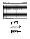
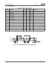
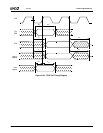
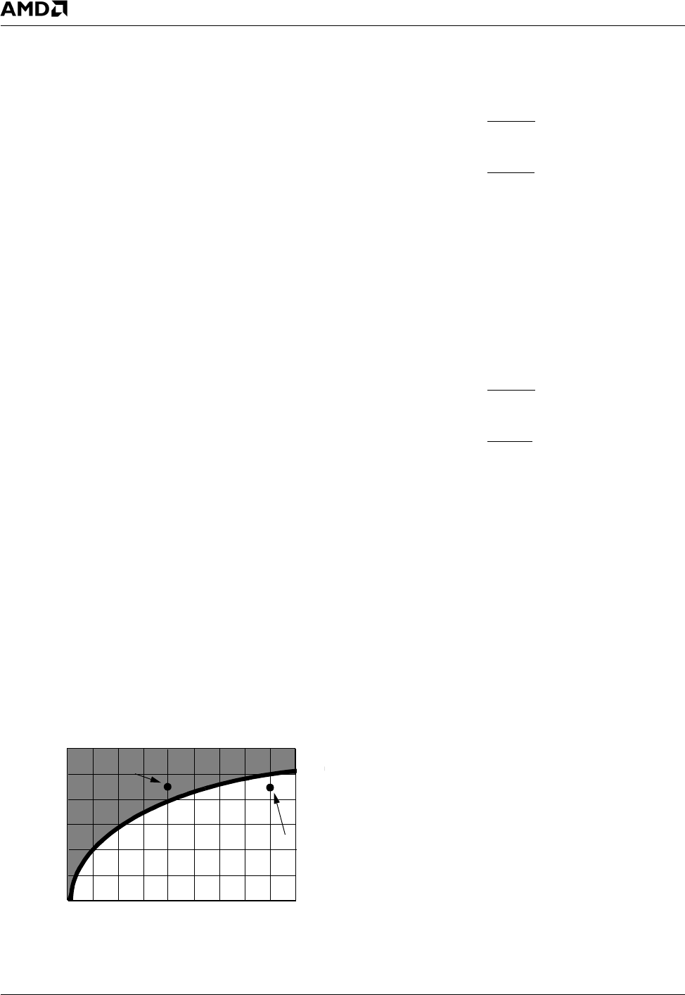
Figure 10-1 is an example of a particular heatsink under
consideration
Figure 10-1. Heatsink Example
Example 1
Assume P (max) = 5W and T
A
(max) = 40°C.
Therefore:
θ
CA
= 9
The heatsink must provide a thermal resistance below 9°C/
W. In this case, the heatsink under consideration is more
than adequate since at 5W worst case, it can limit the case
temperature rise above ambient to 40°C (θ
CA
=8).
Example 2
Assume P (max) = 9W and T
A
(max) = 40°C.
Therefore:
θ
CA
= 5
In this case, the heatsink under consideration is NOT ade-
quate to limit the case temperature rise above ambient to
45°C for a 9W processor.
For more information on thermal design considerations or
heatsink properties, refer to the Product Selection Guide
of any leading vendor of thermal engineering solutions.
Note: The power dissipations P used in these examples
are not representative of the power dissipation of
the SC1200/SC1201 processor, which is always
less than 4 Watts.
0
10
20
30
40
50
24 68
10
θ
CA = 45/9 = 5
Heat Dissipated - Watts
θ
CA = 45/5 = 9
Mounting Surface Temperature
Rise Above Ambient – °C
θ
CA
=
T
C
− T
A
P
θ
CA
=
85 − 40
5
θ
CA
=
T
C
− T
A
P
θ
CA
=
85 − 40
9