


74 AMD Geode™ SC1200/SC1201 Processor Data Book
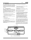
General Configuration Block
32579B
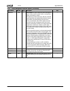
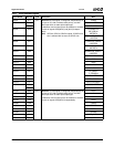
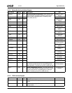
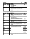
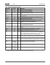
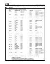
23 TFTPP (TFT/Parallel Port). Determines whether certain balls are used for TFT/VOP or PP/ACB1. This bit is set to 1 at
power-on if the TFT_PRSNT strap (ball P29) is pulled high.
Ball # 0: PP/ACB1/FPCI 1: TFT/VOP
Name Add’l Dependencies Name Add’l Dependencies
H2 / D10 GPIO1 PMR[13] = 0 TFTD12 PMR[15] = 0
IOCS1# PMR[13] = 1 GPIO1 PMR[15] = 1 and PMR[13] = 0
IOCS1# PMR[15] = 1 and PMR[13] = 1
H3 / A9 GPIO20 PMR[7] = 0 TFTD0 PMR[15] = 0
DOCCS# PMR[7] = 1 GPIO20 PMR[15] = 1 and PMR[7] = 0
DOCCS# PMR[15] = 1 and PMR[7] = 1
J4 / A10 GPIO17 PMR[5] = 0 TFTDCK PMR[15] = 0
IOCS0# PMR[5] = 1 GPIO17 PMR[15] = 1 and PMR[5] = 0
IOCS0# PMR[15] = 1 and PMR[5] = 1
T1 / B17 BUSY/WAIT# Note 1 TFTD3 PMR[15] = 0 and Note 1
F_C/BE1# Note 2 VOPD2 PMR[15] = 1 and Note 1
T3 / D17 PE Note 1 TFTD14 Note 1
F_C/BE2# Note 2
T4 / C17 SLCT Note 1 TFTD15 Note 1
F_C/BE3# Note 2
U1 / A18 PD7 Note 1 TFTD13 Note 1
F_AD7 Note 2
U3 / B18 ACK# Note 1 TFTDE PMR[15] = 0 and Note 1
FPCICLK Note 2 VOPCK PMR[15] = 1 and Note 1
V1 / C18 PD4 Note 1 TFTD10 Note 1
F_AD4 Note 2
V2 / C19 PD5 Note 1 TFTD11 Note 1
F_AD5 Note 2
V3 / A20 PD6 Note 1 TFTD1 PMR[15] = 0 and Note 1
F_AD6 Note 2 VOPD0 PMR[15] = 1 and Note 1
W1 / B20 SLIN#/ASTRB# Note 1 TFTD16 Note 1
F_IRDY# Note 2
W2 / C20 PD3 Note 1 TFTD9 Note 1
F_AD3 Note 2
W3 / D20 PD2 Note 1 TFTD8 PMR[15] = 0 and Note 1
F_AD2 Note 2 VOPD7 PMR[15] = 1 and Note 1
Y1 / A21 PD1 Note 1 TFTD7 PMR[15] = 0 and Note 1
F_AD1 Note 2 VOPD6 PMR[15] = 1 and Note 1
Y3 / B21 INIT# Note 1 TFTD5 PMR[15] = 0 and Note 1
SMI_O Note 2 VOPD4 PMR[15] = 1 and Note 1
AA1 / C21 PD0 Note 1 TFTD6 PMR[15] = 0 and Note 1
F_AD0 Note 2 VOPD5 PMR[15] = 1 and Note 1
AA3 / D21 ERR# Note 1 TFTD4 PMR[15] = 0 and Note 1
F_C/BE0# Note 2 VOPD3 PMR[15] = 1 and Note 1
AB1 / A22 STB#/WRITE# Note 1 TFTD17 None
F_FRAME# Note 2
AB2 / D22 AFD#/DSTRB# Note 1 TFTD2 PMR[15] = 0 and Note 1
INTR_O Note 2 VOPD1 PMR[15] = 1 and Note 1
AJ13 / N31 AB1C None GPIO20 PMR[15] = 0 and PMR[7] = 0
DOCCS# PMR[15] = 0 and PMR[7] = 1
AB1C PMR[15] = 1 (Note 3)
AL12 / N30 AB1D None GPIO1 PMR[15] = 0 and PMR[13] = 0
IOCS1# PMR[15] = 0 and PMR[13] = 1
AB1D PMR[15] = 1
AL16 / V30 GXCLK PMR[29] = 0 FP_VDD_ON PMR[15] = 0
TEST3 PMR[29] = 1 GXCLK PMR[15] = 1
Note: 1. PMR[27] = 0 and FPCI_MON = 0
2. PMR[27] = 1 or FPCI_MON = 1
3. ACCESS.bus interface 1 is not available if PMR[23] = 1 and PMR[15] = 0.
4. If FPCI_MON strap is enabled, the TFT_PRSNT strap should be pulled low.
Table 4-2. Pin Multiplexing, Interrupt Selection, and Base Address Registers (Continued)
Bit Description