


356 AMD Geode™ SC1200/SC1201 Processor Data Book
Video Processor Module - Video Processor Registers - Function 4
32579B
Offset C08h-C0Bh Timing & Encoder Control 3 Register Reset Value: 00000000h
31:5 Reserved.
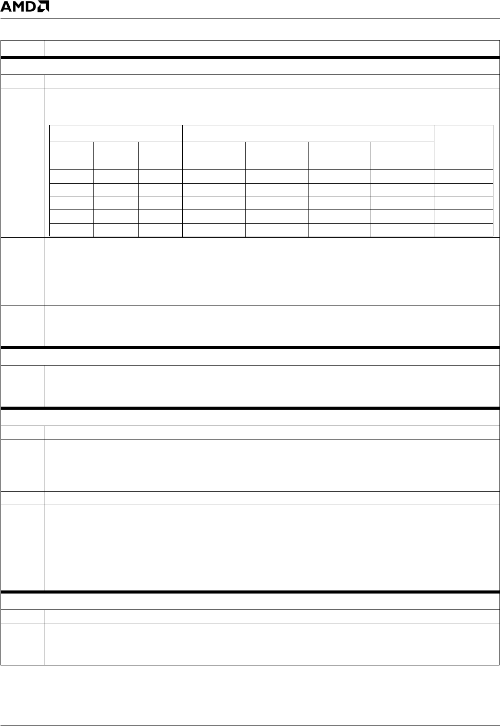
4:3 TV DAC Mode Bits [1:0]. Determines signal order of the TV DAC outputs. Used in conjunction with TV DAC Mode Bit 2
(F4BAR0+Memory Offset C04h[30]).
2:1 SyncMode. Determines where sync is output in SCART mode.
00: Reserved.
01: Sync is added to TVG.
10: Sync is output on the CVBS signal.
11: Reserved.
0 CS (Component Setup).
0: No setup is applied.
1: A 7.5 IRE setup is applied to the YCbCr output.
Offset C0Ch-C0Fh Subcarrier Frequency Register Reset Value: 21F07C1Fh
31:0 SCFREQ (Subcarrier Frequency). Defines the subcarrier frequency.
The value programmed is: round(fsc/fclk x 2
32)
where fsc is the desired subcarrier frequency, and fclk is the clock frequency (27 MHz).
Offset C10h-C13h Display Position Register Reset Value: 00120071h
31:25 Reserved.
24:16 VSTART (Vertical Start). Defines the vertical start position of the top field, relative to the start of VSYNC (line 1 for PAL, line
4 for NTSC).
For 480-line NTSC this field is set to 18 (12h).
For 576-line PAL this field is set to 22 (16h).
15:10 Reserved.
9:0 HSTART (Horizontal Start). Defines the start of active video relative to the start of the line (hcount = 0) in 13.5 MHz clock
periods. The number programmed is START − 9.
For example:
NTSC: Active video starts a nominal 122 13.5 MHz clock periods after the start of line.
The number programmed is 113 (71h).
PAL: Active video starts 132 13.5 MHz clock periods after the start of line.
The number programmed is 123 (7Bh).
Offset C14h-C17h Display Size Register Reset Value: 00EF02CFh
31:25 Reserved.
24:16 DISPHEIGHT (Display Height). Defines the height of a displayed field in lines. Programmed value equals LINE − 1.
For 720x480 NTSC, set to 239 (EFh).
For 720x576 PAL, set to 287 (11Fh).
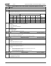
Table 7-9. F4BAR0+Memory Offset: Video Processor Configuration Registers (Continued)
Bit Description
TV DAC Mode Bits [2:0] Ball No.
Mode
C04h[30] C08h[4] C08h[3] D24 A24 C23 A23
x x 0 CVBS SVY SVC CVBS Super Video
0 0 1 CVBS TVR TVB TVG SCART
0 1 1 TVB CVBS TVR TVG SCART
1 0 1 CVBS Cb Cr Y YCbCr
1 1 1 Cr CVBS Cb Y YCbCr