


AMD Geode™ SC1200/SC1201 Processor Data Book 353
Video Processor Module - Video Processor Registers - Function 4
32579B
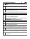
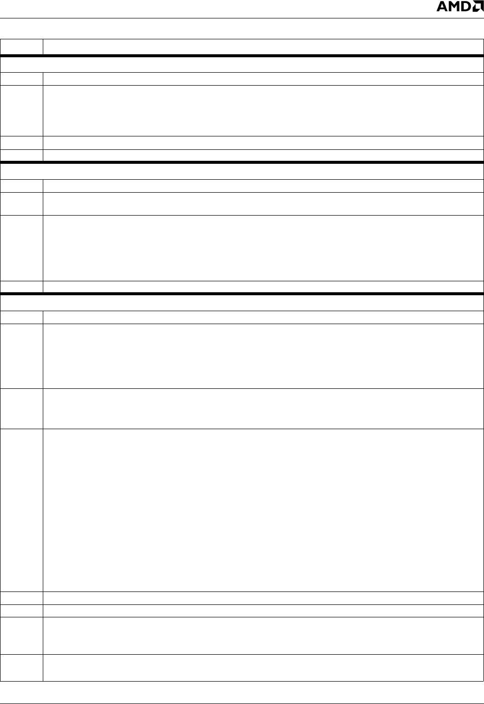
Offset 80Ch-80Fh Display Line End Register (R/W) Reset Value: 00000000h
31:28 Reserved.
27:16 H_DISP_END (Horizontal Display End). Specifies the horizontal display end on a TV screen. The value is calculated
according to the following formula:
H_DISP_END = H_DISP_START + (Display_Active) + 512 - (H_TOTAL / 2)
Display_Active is the active number of pixels on a TV (i.e., 720).
15:9 Reserved.
8:0 VER_DISP (Vertical Display). Specifies the total number of display lines per field on a TV screen.
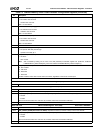
Offset 810h-813h Horizontal Pre Encoder Scale Register (R/W) Reset Value: 00000000h
31 Reserved. Must be set to 0.
30:24 PE_SCALE_STEP. Scale step of the pre-encoder scaler. The programmed value needs to be 64/(scale factor). Meaning,
use 64 for no scaling, use 58 for 11/10 upscale, or use 70 for 11/12 downscale.
23:22 Y/C Delay. Used to calibrate Y/C delay.
00: No change in delay
01: Luminance is delayed one pixel time (2 TV Encoder clock cycles).
10: Chrominance is delayed one pixel time (2 TV Encoder clock cycles).
11: Chrominance is delayed two pixel times (4 TV Encoder clock cycles)
21:0 Reserved. Set to 0.
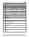
Offset 814h-817h Horizontal Scaling/Control Register (R/W) Reset Value: 00000000h
31 Reserved.
30:29 FLICKER_FILT_CNTRL (Flicker Filter Control).
00: Flicker filter with 1/4, 1/2, 1/4. This setting must be used to enable the flicker filter when progressive blending is used.
01: Flicker filter with 1/2, 1, 1/2. This setting must be used to enable the flicker filter when interlaced blending is used.
10: Flicker filter disabled.
11: Reserved.
28 H_REF_SEL (Horizontal Reference Select). Selects reference for the horizontal display position.
0: HSYNC generated in the TVOUT timing generator.
1: HSYNC generated in the TV Encoder block. This is the recommended setting.
27:24 EX_RES_CTL (External Reset Control). To maintain field synchronization between the GX1 graphics module and the TV
encoder, the GX1 VSYNC signal can reset the TV encoder timing generator. This register selects the field interval between
resets.
0000: Once every odd field.
0010: Once every even field.
0101: The next odd field. Returns 0101 until the reset event occurs. After the reset event, returns 0100 and no further
resets occur.
0111: The next even field. Returns 0111 until the reset event occurs. After the reset event, returns 0110 and no further
resets occur.
1000: Once every programmable number of odd fields. See bits [15:12] and 11 (External Reset Interval bits).
1010: Once every programmable number of even fields. See bits [15:12] and 11 (External Reset Interval bits).
1110: Once every field.
All other settings: Reserved.
23:21 Reserved.
20:16 Reserved. Must be set to 2.
15:12 EX_RES_INTRVl (External Reset Interval). Specifies the interval (the number of frames) between resets of the encoder
minus 1 (i.e., a setting of 1 results in a reset to the encoder every 2 frames (or 4 fields)).
These bits are relevant only if bits [27:24] (EX_RES_CTL) are set to 1000 or 1010.
11 EX_RES_INTRVl_16 (External Reset Interval + 16). Adds 16 frames to the external Reset Interval.
These bits are relevant only if bits [27:24] (EX_RES_CTL) are set to 1000 or 1010.
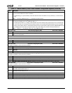
Table 7-9. F4BAR0+Memory Offset: Video Processor Configuration Registers (Continued)
Bit Description