MFJ-1278B MULTI-MODE RADIO INTERFACING
HANDHELD RADIO CONNECTION
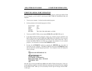
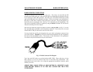
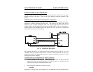
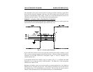
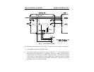
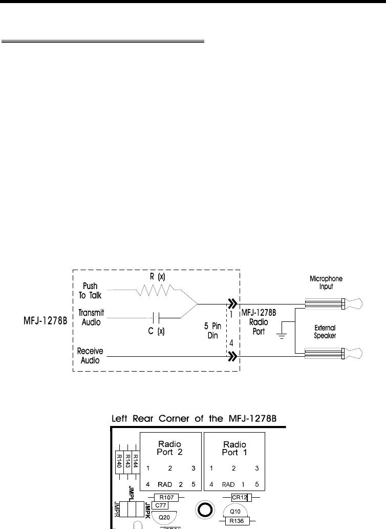
Some HTs key the transmitter by drawing a small amount of current from the microphone
input pin (see Fig. 3-3 below). Radios with this type of special keying circuit are ICOM-2AT
(tm) and Yaesu FT-x09, FT-x3, FT-727 (tm) and others.
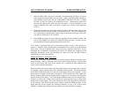
Appendix A at the end of this instruction manual provided pin designation for some of the
radios. Also consult the instruction manual of your radio.
If your HT has this type of microphone circuit, you can wire the microphone like the one
shown in Fig. 3-3 or you can remove the cover of the MFJ-1278B and install a shorting
jumper at JMP L for Radio Port 1 or JMP K for Radio Port 2. Installing JMP K or JMP L
will eliminating the need of soldering "Cx" and "Rx" to the microphone cable. "Cx" and
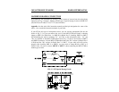
"Rx" are installed on the MFJ-1278B mother board. Fig. 3-4 shows the location of JMP L
and JMP K connectors. On the MFJ-1278B mother board, the "Rx" resistor for Radio Port 1
is R140 and the "Rx" resistor for Radio Port 2 is R107. If your radio still will not key
properly after installing JMP L or JMP K, you may need to change R140 or R107 to a
smaller value. Be sure to remove JMP K or JMP L when connecting the MFJ-1278B to
another type of radio.
FIG. 3-3 HT Special Keying Circuit


