


MFJ-1278B MULTI-MODE HARDWARE
Pin 13 Receive Clock Input
This pin is tied to the SIO receive clock input pin. It expects a clock at the desired data rate
(1200 Hz for 1200 baud), of the proper phase relationship to the received data. This pin is
normally jumpered to pin 14 when the on-board modem is used.
Pin 14 Receive Clock Output
This pin is the received data clock signal derived from the NRZI-to-NRZ state machine. This
pin is normally jumpered to pin 13 when the on-board modem is used.
Pin 15 MFJ-1278B Ground Reference
This pin ties to the MFJ-1278B digital ground system, at the SIO.
Pin 16 Turbo LED output
This pin is used to connect the Turbo LED on the mother board to the external modem board.
When this pin is high (+5Vdc), the Turbo LED will light.
Pin 17 Receive Data Input
This pin is the received data input to the NRZI-to-NRZ state machine. This pin is normally
jumpered to pin 18 when the on-board modem is used.
Pin 18 Receive Data Output
This pin provides receive data from the on-board modem. This pin is normally jumpered to
pin 17 when the on- board modem is used.
Pin 19 Transmit Data Output
This line is the NRZ or NRZI (depending on the state of JMP11) data output. This pin is
normally jumpered to pin 20 when the on-board modem is used.
Pin 20 Transmit Data Input
This input line accepts data to be be transmitted by the modem. This pin is normally
jumpered to pin 19 when the on-board modem is used.
If you elect to use an off-board modem, be sure to properly shield the interconnecting cables
for RFI protection.
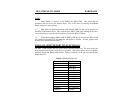
HF TUNING INDICATOR
The MFJ-1278B has a built-in tuning indicator for HF operation. It is set for a center
frequency of 2210 Hz. The incoming audio frequency is centered at 2210 Hz. This is