


MFJ-1278B MULTI-MODE RADIO INTERFACING
CW INSTALLATION
The MFJ-1278B user can send and receive CW by using your computer keyboard. However,
the MFJ-1278B expands CW operating fun by allowing you to connect an iambic paddle to
the KEY input jack of the MFJ-1278B. This feature allows you to use the MFJ-1278B as a
CW memory keyer. So now the user can operate CW from either the computer or an iambic
paddle. Connect the MFJ-1278B for CW operation as follows:
Keying Connection
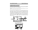
Connect a two-conductor shielded cable from the Keying Output jack of the MFJ-1278B to
the keying input of your radio. The keying output jacks of the MFJ-1278B accept a standard
RCA phono plug.
The keying output of the MFJ-1278B provides both the "Direct" or "Grid Block" type of
keying output for your radio. The default output setting for the MFJ-1278B is "Direct" type
keying. If your radio requires "Grid Block" type of keying, you may set the keying output to
"Grid Block" by moving the shorting jumper on JMP22 from positions 2 & 3 to positions to 1
& 2. See Appendix G at the end of this manual to locate JMP 22 on the MFJ-1278B mother
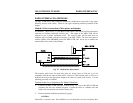
board. After properly connecting the keying cable, you must determine what kind of keying
circuit your radio has. If your radio is a solid state or cathode keyed type, then you should
use the DIRECT keying output. If your radio is tube type you should use the GRID
BLOCK keying output. If you are unsure of which output to use, try both outputs. The
keying outputs of the MFJ-1278B are diode protected. If the wrong output is used you will
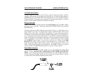
notice a constant key down effect on the transmitter. The DIRECT output keys a positive
voltage to ground. The GRID BLOCK output keys a negative voltage to ground.
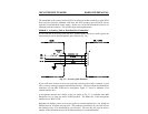
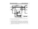
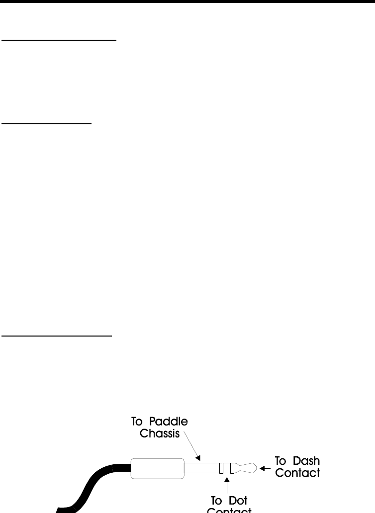
Key Paddle Connection
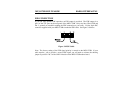
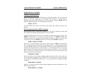
The KEY paddle input jack of the MFJ-1278B accepts a 3.5mm stereo plug. (Radio Shack
Part No. 274-284). DO NOT USE A MONO plug, IT WILL SHORT OUT THE KEY
INPUT. A two conductor fully shielded cable should be used. Wire the tip of the plug for
the dash contact and the ring of the plug for the dot contact (See Figure 3-8 below). Be sure
to use the shield of the cable for the paddle ground contact.