MFJ-1278B MULTI-MODE APPENDIX B MODEM CALIBRATION
5. Command the MFJ-1278B to do a demodulator calibration by typing "RXCAL <CR>".
6. CAREFULLY adjust R113 until the DCD LED on the front panel is fully illuminated.
NOTE: The threshold control on the MFJ-1278B must be set to a position which will allow
the DCD circuit to function properly. A setting approximately 1/3 to 1/2 of the total
range starting from maximum CCW should be adequate.
Continue to VERY CAREFULLY adjust R113 until the STA and CON LEDs on the front
panel either change state very slowly (alternate which one is lit) or until both are
simultaneously illuminated.
NOTE: This is a very critical adjustment. It is very unlikely that you will be able to cause
both LEDs to be turned on simultaneously, for longer than a very brief instant. Just
fine tune R113 very carefully, and notice the action between the STA and CON leds.
If they flash back and forth this is acceptable.
7. Return the MFJ-1278B to command mode by typing a "Q".
This completes demodulator center frequency alignment using the built in calibration
software. If there were any problems in the preceeding procedure, then DO NOT go beyond
this point. If you do the calibration will be inaccurate.
Now that the demodulator and modulator are properly aligned to one another, the tuning
indicator can be set for proper center indication.
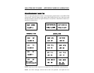
Tuning Indicator Alignment
This procedure adjusts the tuning indicator so that it correctly indicates when a signal is
properly tuned in relation to the demodulator center frequency. In order for the Tuning
Indicator to be properly aligned the above calibration must be done properly, otherwise you
will align the Tuning Indicator improperly.
NOTE: The tuning indicator should ONLY be adjusted in reference to the 300 baud 200 Hz
shift modem used for HF packet and RTTY. If adjusted for this modem, it will
indicate with sufficient accuracy for all other modes.
If you have not just finished aligning the modem as per the above instructions, do so now.
Otherwise you may be aligning the tuning indicator to incorrect calibration settings.
Alignment Procedure
1. Install push on jumpers at JMP 4 and JMP 7, if they are not still in place from the
modem alignment procedure.


