


9-3
9-2 Common Specifications
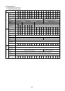
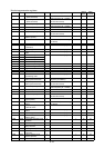
Item Explanation
Control method Sinusoidal wave PWM control (with V/F control, torque vector control, PG feedback vector control (option))
Maximum
frequency
G11S: 50 to 400Hz variable setting P11S: 50-120Hz variable setting
Base
frequency
G11S: 25 to 400Hz variable setting P11S: 25-120Hz variable setting
Starting
frequency
0.1 to 60Hz variable setting Holding time: 0.0 to 10.0 s
Carrier
frequency
G11: 0.75 to 15kHz (75HP or less) 0.75 to 10kHz (100HP or more)
P11: 0.75 to 15kHz (30HP or less) 0.75 to 10kHz (40 to 100HP) 0.75 to 6kHz (125HP or more)
Accuracy
(stability)
Analog setting: +/- 0.2% or less of the max. Frequency (at 25℃ (77°F) +/- 10℃ (50°F))
Digital setting: +/- 0.01% or less of the max. Frequency (-10℃ (14°F) to +5℃ (122°F))
Output frequency
Setting
resolution
Analog setting: 1/1000 of max. frequency (30HP or less) 1/3000 of max. frequency (40HP or more)
Digital setting: 0.01Hz (99.99Hz or less), 0.1Hz (100.0Hz or more)
Voltage/frequency
characteristics
Output voltage at base frequency can be adjusted separately, such as 80 to 240V (230V series) or 320 to 480V
(460V series).
Output voltage at max. frequency can be adjusted separately, such as 80 to 240V (230V series) or 320 to 480V
(460V series).
Torque boost Auto: Optimum control corresponding to the load torque.
Manual: 0.1 to 20.0 code setting (energy saving reduced torque, constant torque (strong), etc.)
Accelerating/decelerating
time
0.01 to 3600s
Four accelerating and decelerating time settings are possible independent of each other by selecting digital input
signals.
In addition to linear acceleration and deceleration, either S-shaped acceleration/deceleration (weak/strong) or
curvilinear acceleration/deceleration can be selected.
DC injection braking Starting frequency: 0.0 to 60.0Hz, braking time: 0.0 to 30.0s,
Braking level: 0 to 100% (G11S), 0-80% (P11S)
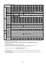
Control
Function equipped Frequency upper and lower limiter, bias frequency, frequency gain, jump frequency, pick-up operation, restart
after momentary power failure, switching operation from line to inverter, slip compensation control, automatic
energy saving operation, regeneration avoiding control, droop control, torque limiting (2-step), torque control, PID
control, second motor switching, cooling fan ON/OFF control.
Operation method
Keypad panel: Run by , keys, stop by key
Terminal input: Forward/stop command, reverse/stop command, coast-to-stop command, alarm reset,
acceleration/deceleration selection, multistep frequency selection, etc.
Frequency setting
Keypad panel: Setting by , keys
External potentiometer: External freq.setting POT (VR) (1 to 5kΩ)
Analog input: 0 to +10V (0 to +5V), 4 to 20mA, 0 to +/- 10V (FWD/REV operation)
+10 V to 0 (reverse operation), 20 to 4mA (reverse operation)
UP/DOWN control: Frequency increases or decreases as long as the digital input signal is turned on.
Multistep frequency selection: Up to 15 steps are selectable by a combination of digital input signals (four kinds).
Link operation: Operation by RS-485 (standard).
Program operation: Pattern operation by program
Jogging operation: Jogging operation by , key or digital input signals
Operation
Operation status signal Transistor output (4 signals): Running, frequency arrival, frequency detection, overload early warning, etc.
Relay output (2 signals): Alarm output (for any fault), multi-purpose relay output signals
Analog output (1 signal): Output frequency, output current, output voltage, output torque, power consumption, etc.
Pulse output (1 signal): Output frequency, output current, output power, output torque, power consumption, etc.
Digital display (LED) Output frequency, setting frequency, output current, output voltage, motor synchronous speed, line speed, load
rotation speed, calculated torque value, power consumption, calculated PID value, PID command value, PID
feedback value, alarm code
Liquid crystal display (LCD) Operation information, operational guide, functional code/name/setting data, alarm information, tester function,
motor load rate measuring function (Maximum/average current (rms) during measuring period, maintenance
information (Integrated operation hours, capacitance measurement for main circuit capacitors, heat sink
temperature, etc.))
Language Six languages (Japanese, English, German, French, Spanish, and Italian)
Indication
Lamp display Charging (voltage residual), operation indication
Protective functions
Overcurrent, short-circuit, ground fault, overvoltage, undervoltage, overload, overheating, blown fuse, motor
overload, external alarm, input open-phase, output open-phase (when tuning), braking resistor protection, CPU
and memory error, keypad panel communication error, PTC thermistor protection, surge protection, stall
prevention, etc.
Installation location Indoor, altitude less than 3300ft (1000m), free from corrosive gas, dust, and direct sunlight (Pollution degree 2)
Ambient temperature
-10℃ (14°F) to +50℃ (122°F) (ventilating cover must be removed under conditions exceeding +40℃ (104°F)
for models rated at 30HP or less)
Ambient humidity 5 to 95%RH (no condensation)
Air pressure Operation/storage :86 to 106 kPa
Transport :70 to 106 kPa
Vibration
0.12inch(3mm) at from 2 to less than 9Hz, 9.8m/s
2
at from 9 to less than 20Hz,
2m/s
2
at from 20 to less than 55Hz, 1m/s
2
at from 55 to less than 200Hz,
Ambient
temperature
-25℃ (-13°F) to +65℃ (149°F)
Environment
Storage
Ambient humidity 5 to 95%RH (no condensation)
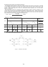
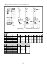
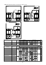
FWD
FWD
REV
REV
STOP
∨
∧