


5-37
Instantaneous switching to another power line (when the
power of an operating motor is cut off or power failure
occurs) creates a large phase difference between the
line voltage and the voltage remaining in the motor,
which may cause electrical or mechanical failure. To
rapidly switch power lines, write the remaining voltage
attenuation time to wait for the voltage remaining in the
motor to attenuate. This function operates at restart
after a momentary power failure.
H 1 3 R E S T A R T T
Setting range: 0.1 to 5.0 seconds
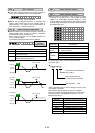
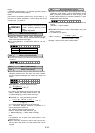
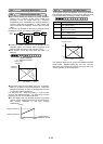
When the momentary power failure time is shorter than
the wait time value, a restart occurs following the wait
time. When the power failure time is longer than the
wait time value, a restart occurs when the inverter is
ready to operate (after about 0.2 to 0.5 second).
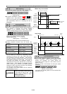
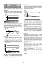
This function determines the reduction rate of the output
frequency for synchronizing the inverter output frequency
and the motor speed. This function is also used to
reduce the frequency and thereby prevent stalling under
a heavy load during normal operation.
H 1 4 F A L L R A T E
Setting range: 0.00, 0.01 to 100.00 Hz/s
When 0.00 is set, the frequency is reduced according to
the set deceleration time.
Note:
A too large frequency reduction rate is may temporarily
increase the regeneration energy from the load and
invoke the overvoltage protective function. Conversely,
a rate that is too small extends the operation time of the
current limiting function and may invoke the inverter
overload protective function.
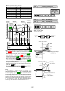
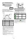
This function is for when 2 (deceleration-to-stop at power
failure) or 3 (operation continuation) is set to "F14
Restart after momentary power failure (operation
selection)." Either function starts a control operation if
the main circuit DC voltage drops below the set operation
continuation level.
H 1 5 H O L D V
Setting range 230 V series: 200 to 300V
460 V series: 400 to 600V
When power supply voltage to the inverter is high,
control can be stabilized even under an excessive load
by raising the operation continuation level. However,
when the level is too high, this function activates during
normal operation and causes unexpected motion.
Please contact Fuji electric when changing the initial
value.
As the power to an external operation circuit (relay
sequence) and the main power to the inverter is
generally cut off at a power failure, the operation
command issued to the inverter is also cut off. This
function sets the time an operation command is to be
held in the inverter. If a power failure lasts beyond the
self-hold time, power-off is assumed, automatic restart
mode is released, and the inverter starts operation at
normal mode when power is applied again. (This time
can be considered the allowable power failure time.)
H 1 6 S E L F H O L D T
Setting range: 0.0 to 30.0 seconds, 999
When "999" is set, an operation command is held (i.e.,
considered a momentary power failure) while control power
in the inverter is being established or until the main circuit
DC voltage is about 100Vdc.
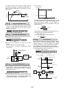
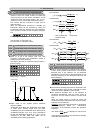
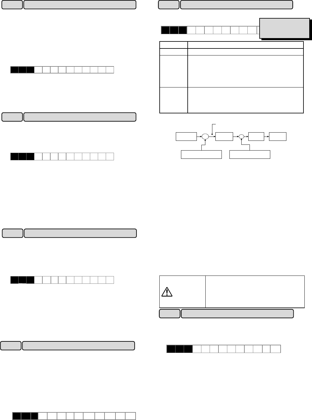
This function controls motor torque according to a
command value.
Set value
Operation
0 Inactive (Operation by frequency command)
1 Torque control active
0 to +10V analog voltage input to terminal 12
and the direction of rotation (FWD or REV) is
used for the torque command value. 0 is
used for 0 to -10V.
2 Torque control active
-10 to +10V analog voltage input to terminal
12 and the direction of rotation (FWD or
REV) is used for the torque command value.
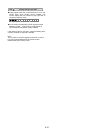
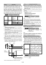
x
Forward command
Reverse command
Torque
limitation
Detected torque
current
Regulator
Voltage at
terminal 12
Output
frequency
+
-
Torque command value
Torque control block diagram
The torque command value is +200% when the voltage at
terminal 12 is +10V and is -200% when the voltage is -10V.
Auto tuning(P04/A13: 2) should be done to use this
function.
In torque control, the torque command value and motor
load determine the speed and direction of rotation.
When the torque is controlled, the upper limit of
frequency refers to the minimum value among the
maximum frequency , the frequency limiter (upper limiter)
value, and 120 Hz. Maintain the frequency at least
one-tenth of the base frequency because torque control
performance deteriorates at lower frequencies.
If the operation command goes off during a torque
control operation, the operation is switched to speed
control and the motor decelerates-to-stop. At this time,
the torque control function does not operate.
This function cannot be used when the motor 2 is
selected.
This function cannot be used for FRN-P11S.
WARNING
The malfunction may be occurred
when the set torque is mistaken. (up
to upper frequency, maximum
frequency or 120Hz)
as accident may result.
This function automatically extends accelerating time
against acceleration operation of 60 seconds or longer to
prevent an inverter trip resulting from a temperature rise
in inverter due to overcurrent.
Set value 0: Inactive
1: Active
(When the active drive function is activated, the
acceleration time is three times the selected time.)
H 1 8
T R Q C T R L
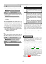
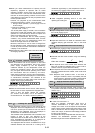
H 1 9 AUT R E D
H19 Active drive
H16
Auto-restart (OPR command selfhold time)
H13 Auto-restart (Restart time)
H15 Auto-restart (Holding DC voltage)
H14 Auto-restart (Freq. fall rate)
H18 Torque control
Related functions
E01toE09
(Set value: 23)