


5-28
This function makes the set frequency jump so that the
inverter's output frequency does not match the
mechanical resonance point of the load.
Up to three jump points can be set.
This function is ineffective when jump frequencies 1 to 3
are set to 0Hz.
A jump does not occur during acceleration or deceleration.
When a jump frequency setting range overlaps another
range, both ranges are added to determine the actual
jump area.
Setting range
G11S : 0 to 400Hz
P11S : 0 to 120Hz
In 1Hz steps (min.)
Setting range
0 to 30Hz
In 1Hz steps (min.)
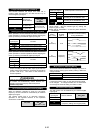
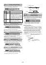
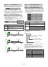
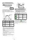
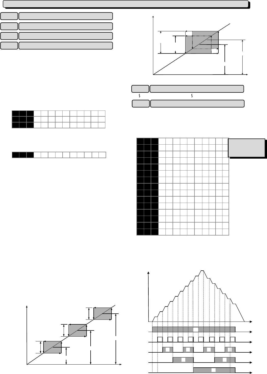
To avoid the resonance of the motor driving frequency to
the peculiar vibration frequency of the machine, the jump
frequency band can be set to the output frequency up to
three point.
During accelerating, an internal set frequency is kept
constant by the lower frequency of the jump frequency
band when a set frequency enters the jump frequency
band. This means that the output frequency is kept
constant according to an internal set frequency.
When a set frequency exceeds the upper bound of the
jump frequency band, an internal set frequency reaches
the value of a set frequency. The output frequency
accelerates up to a set frequency while passing the jump
frequency band according to the acceleration time at this
time.
During decelerating, it has a relation opposite to
accelerating. Refer to figure below.
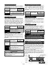
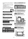
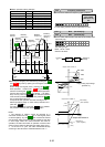
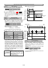
When two jump frequency bands or more come in
succession mutually, the lowest and highest frequency
become the lower bound and the upper bound frequency
of an actual jump frequency band respectively among
them. Refer to upper right figure.
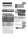
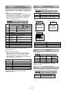
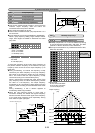
Multistep frequencies 1 to 15 can be switched by turning
on and off terminal functions SS1, SS2, SS4, and SS8.
(See E01 to E09 for terminal function definitions.)
OFF input is assumed for any undefined terminal of SS1,
SS2, SS4, and SS8.
Setting range
G11S: 0.00 to 400.00Hz
P11S: 0.00 to 120.00Hz
In 0.01Hz steps (min.)
Output frequency
(Hz)
ON ON ON ON
ON
ON ON
ON
ON
ON ON
ON
ON
ON ON
ON
C05
FWD-P24
SS1-P24
SS2-P24
SS4-P24
SS8-P24
C06
C07
C08
C09
C10
C11
C12
C13
C14
C15
C16
C17
C18
C19
Internal set frequency (Hz)
Actual
j
ump width
Jump frequency 2
Jump frequency 1
Set fre
q
uenc
y
(
Hz
)
Jump frequency
width
C 0 1 J U M P H z 1
C 0 2 J U M P H z 2
C 0 3 J U M P H z 3
C 0 4 J U M P H Y S T R
Internal set frequency (Hz)
Jump frequency 1
Jump frequency
width
Jump frequency
width
Jump frequency
width
Set frequency (Hz)
Jump frequency 2
Jump frequency 3
C 0 5 M U L T I H z - 1
C 0 6 M U L T I H z - 2
C 0 7 M U L T I H z - 3
C 0 8 M U L T I H z - 4
C 0 9 M U L T I H z - 5
C 1 0 M U L T I H z - 6
C 1 1 M U L T I H z - 7
C 1 2 M U L T I H z - 8
C 1 3 M U L T I H z - 9
C 1 4 M U L T I H z 1 0
C 1 5 M U L T I H z 1 1
C 1 6 M U L T I H z 1 2
C 1 7 M U L T I H z 1 3
C 1 8 M U L T I H z 1 4
C 1 9 M U L T I H z 1 5
C
:
Control Functions of Frequency
C01 Jump frequency 1
Jump frequency 2
C03 Jump frequency 3
C04 Jump frequency (Hysteresis)
C02
Related functions
E01 to E09
(Set value:0 to 3
)
C05 Multistep frequency 1
C19 Multistep frequency 15