


5-30
C 3 0 F R E Q C M D 2
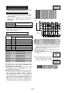
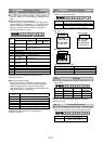
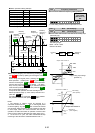
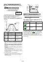
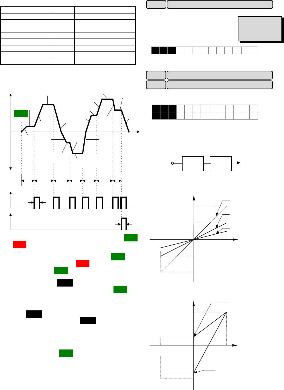
Pattern operation setting example
Function
Set value
Operation frequency to be set
C21 (operation selection)
1
-
C22 (stage 1)
60.0F2
Multistep frequency 1 (C05)
C23 (stage 2)
100F1
Multistep frequency 2 (C06)
C24 (stage 3)
65.5R4
Multistep frequency 3 (C07)
C25 (stage 4)
55.0R3
Multistep frequency 4 (C08)
C26 (stage 5)
50.0F2
Multistep frequency 5 (C09)
C27 (stage 6)
72.0F4
Multistep frequency 6 (C10)
C28 (stage 7)
35.0F2
Multistep frequency 7 (C11)
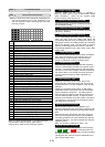
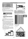
The following diagram shows this operation.
Forward
direction
Reverse
direction
Time
ACC2
ACC1
DEC4
ACC4
ACC3 DEC2
ACC2
ACC4
DEC2
DEC1
60.0S 100S 65.5S
55.0S
50.0S 72.0S
35.0S
0.1S
0.1S
Set
value
:16
Output signals from terminals Y1 to Y5
Output frequency(motor speed)
Multistep
frequency 1
(Stage 1)
Multistep
frequency 2
Multistep
frequency 3
Multistep
frequency 4
Multistep
frequency 5
Multistep
frequency 6
Multistep
frequency 7
(Stage 7)
Set
value
:17
Running and stopping are controlled by pressing the
and keys and by opening and closing the control
terminals.
When using the keypad panel, pressing the key
starts operation. Pressing the key pauses stage
advance. Pressing the key again restarts operation
from the stop point according to the stages. If an alarm
stop occurs, press the key to release operation
of the inverter protective function, then press the
key to restart stage advance.
If required to start operation from the first stage "C22
Pattern operation (stage 1)," enter a stop command and
press the key.
If an alarm stop occurs, press the key to release
the protective function, then press the key again.
Notes:
1. The direction of rotation cannot be reversed by a
command issued from the key on the keypad panel
or terminal [REV]. Any reverse rotation commands entered
are canceled. Select forward or reverse rotation by the data
in each stage. When the control terminals are used for
operation, the self-hold function of operation command also
does not work. Select an alternate type switch when using.
2. At the end of a cycle, the motor decelerates-to-stop
according to the value set to "F08 Deceleration time 1."
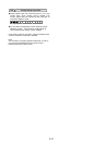
This function selects the frequency setting method.
For the setting method, see the explanation for F01.
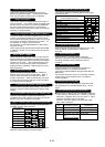
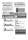
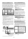
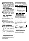
This function sets the Gain and Bias of the analog input
(terminals [12] ).
The setting range :
BIAS: -100 to +100%
GAIN:0.0 to 200%
Terminal
12
Gain Bias
Reference
volta
g
e
-10 0 +10[V]
Output value of Gain 12
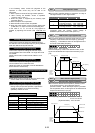
A
nalog input voltage
[terminal 12]
200%
100%
50%
+10V
-10V
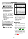
-10 0 +10[V]
Output value of Bias 12
Output value of Gain 12
Bias setting
(when positive)
Bias setting
(when negative)
+10V
(+100%)
-10V
(-100%)
C 3 1 B I A S 1 2
C 3 2 G A I N 1 2
C30 Frequency command 2
C31 Bias (terminal[12])
C32 Gain (terminal[12])
Related functions
E01 to E09
(Set value:11)
F01
FWD
FWD
FWD
FWD
FWD
REV
STOP
STOP
RESET
RESET
RESET