


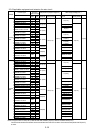
2-14
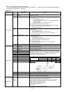
Pulse output
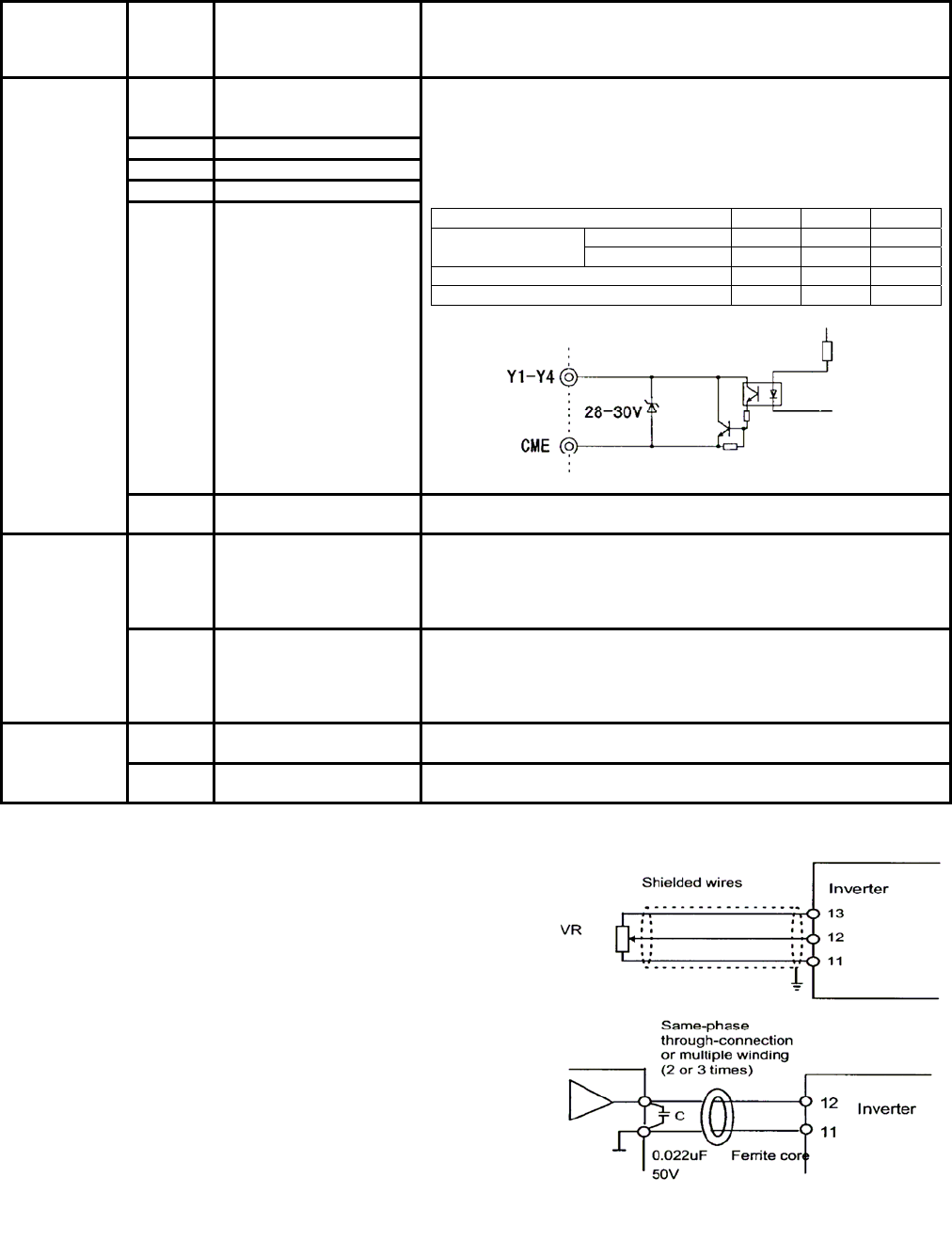
FMP
(CM:
Common
terminal)
Frequency monitor
(pulse waveform output)
Outputs a monitor signal using the pulse waveform.
This signal has the same function as the FMA signal.
Y1 Transistor output1
Y2 Transistor output2
Y3 Transistor output3
Y4 Transistor output4
A running signal, frequency equivalence signal, overload early warning
signal, and other signals from the inverter are output (as transistor
output) to arbitrary ports, For details, see "Setting the Terminal
Functions E20 to E23" in Section 5.2, "Details of Each Function."
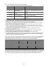
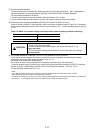
<Specifications of transistor output circuit>
*
Item min. typ. max.
ON level - 2V 3V Operating
voltage
OFF level - 24V 27V
Maximum load current at ON level - - 50mA
Leakage current at OFF level - - 0.1mA
Transistor
output
CME Transistor output
common
Common terminal for transistor output signals
This terminal is insulated from terminals [CM] and [11].
30A,30B,
30C
Alarm output for any fault If the inverter is stopped by an alarm (protective function), the alarm
signal is output from the relay contact output terminal (1SPDT).
Contact rating: 48V DC, 0.5A
An excitation mode (excitation at alarm occurrence or at normal
operation) can be selected.
Relay output
Y5A,Y5C Multipurpose-signal relay
output
These signals can be output similar to the Y1 to Y4 signals above.
The contact rating for any fault is the same as that of the alarm output
above.
An excitation mode (excitation at alarm occurrence or at normal
operation) can be selected.
DX+, DX- RS-485 communication
input-output
Input-output signal terminals for RS-485 communication. UP to 31
inverters can be connected using the daisy chain method.
Communication
SD Communication-cable
shield connection terminal
Terminal for connecting the shield of a cable. The terminal is
electrically floating.
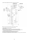
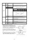
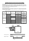
(1)Analog input terminals (13,12,V2,C1,and 11)
①These terminals receive weak analog signals that may be
affected by external noise. The cables must be as short as
possible (66ft (20m) or less), must be shielded, and must
be grounded in principle. If the cables are affected by
external induction noise, the shielding effect may be
improved by connecting the shield to terminal [11].
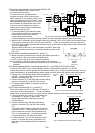
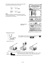
② If contacts must be connected to these circuits, twin
(bifurcated type) contacts for handling weak signals must
be used. A contact must not be connected to terminal
[11].
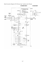
③If an external analog signal output device is connected to
these terminals, it may malfunction as a result of inverter
noise. To prevent malfunction, connect a ferrite core or
capacitor to the external analog signal output device.
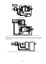
Fig. 2-3-12
Fig. 2-3-13 Example of noise prevention
0k to 5 kΩ