2-19
CAUTION on Magnetic contactor selection (without DCR)
[without DCR]
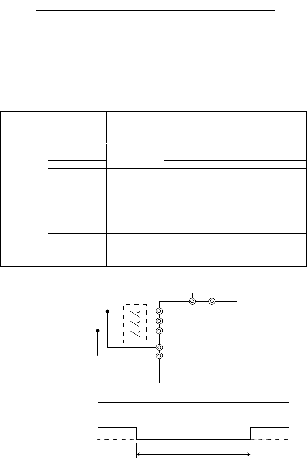
The magnetic contactor should be selected from "Magnetic contactor models" shown in table 2-3-4 to
prevent the welding the magnetic contactor when using the auxiliary power input (R0, T0) and the time
between the magnetic contactor of the main circuit (L1/R, L2/S, L3/T) is OFF and re-turning on is "T off
main circuit re-turning on time" or the less shown in table 2-3-4.
[with DCR or other conditions]
When the inverter which is NOT described in the table 2-3-4 or using with DCR (power-factor
correcting DC reactor), the magnetic contactor is selected from "2-3-5 Applicable equipment and wire
size for main circuit" in chapter 2.
Table 2-3-4 Re-turning on time and recommended magnetic contactor models
Voltage G11S P11S
*1 T off
Re-turning on time [s]
(the time from power OFF to
re-turning on)
*2
Magnetic contactor
models
(without DCR)
FRN002G11S-2UX
54
FRN003G11S-2UX
76
SC-N1
FRN005G11S-2UX
-
108 SC-N2
FRN007G11S-2UX FRN007P11S-2UX
77
FRN010G11S-2UX FRN010P11S-2UX
112
SC-N2S
3-Phase
230V series
FRN015G11S-2UX FRN015P11S-2UX
77 SC-N3
FRN002G11S-4UX
27 SC-5-1
FRN003G11S-4UX
38
FRN005G11S-4UX
-
54
SC-N1
FRN007G11S-4UX FRN007P11S-4UX
43
FRN010G11S-4UX FRN010P11S-4UX
57
SC-N2
FRN015G11S-4UX FRN015P11S-4UX
77
FRN020G11S-4UX FRN020P11S-4UX
112
FRN025G11S-4UX FRN025P11S-4UX
134
SC-N2S
3-Phase
460V series
FRN030G11S-4UX FRN030P11S-4UX
154 SC-N3
Magnetic contactor ON OFF ON
Auxiliary power input supplied
*1 T off
Power supply
L1
/
R
R0
L2/S
T0
L3/T
Inverter
*2
Magnetic
contacto
r
P1 P(+)
without DCR


