9-13
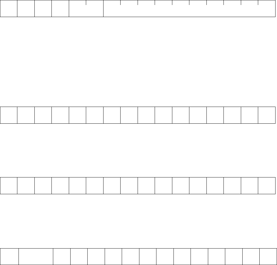
Data format [13] Pattern operation
15 14 13 12 11 10 9 8 7 6 5 4 3 2 1 0
Direction
of rotation
0 Time
Index portion Data portion
0: 1st ACC/DEC time 0: 0.01 X 001–999 (0.00–9.99)
0: FWD 1: 2nd ACC/DEC time 1: 0.1 X 100–999 (10.0–99.9)
1: REV 2: 3rd ACC/DEC time 2: 1 X 100–999 (100–999)
3: 4th ACC/DEC time 3: 10 X 100–999 (1000–9990)
Example) If C22 (Stage1) = 10.0s R2 (10s, reverse rotation, acceleration time 2/deceleration time 2)
Since 10.0 = 0.1 X 100 > 9000
H
+ 0400
H
+ 0064
H
= 9464
H
Data format [14] Operation command
15 14 13 12 11 10 9 8 7 6 5 4 3 2 1 0
RST 0 0 0 0 X9 X8 X7 X6 X5 X4 X3 X2 X1 REV FWD
(All bit are ON by 1)
Example If S06 (operation command) = FWD, X1 and X5 = ON
0000 0000 0100 0101
b
= 0045
H
Data format [15] Universal output terminal
15 14 13 12 11 10 9 8 7 6 5 4 3 2 1 0
0 0 0 0 0 0 0 0 0 0 0 Y5 Y4 Y3 Y2 Y1
(All bit are ON by 1)
Example) If M15 (Universal output terminal)=Y1 and Y5 = ON
0000 0000 0001 0001
b
= 0011
H
Data format [16] Operating state
15 14 13 12 11 10 9 8 7 6 5 4 3 2 1 0
BUSY WR RL ALM DEC ACC IL VL TL NUV BRK INT EXT REV FWD
(All bit are ON or active by 1)
FWD: Forward operation IL: Current limiting
REV: Reverse operation ACC: Under acceleration
EXT: DC braking active (or pre-excitation) DEC: Under deceleration
ALM: Inverter fault
INT: No Output RL: Transmission valid
BRK: Braking active WR: Function writing privilege
NUV: DC link voltage is established 0: Keypad panel
(undervoltage at 0) 1: RS-485
TL: Torque limiting 2: Fieldbus (option)
VL: Voltage limiting BUSY: Processing data write


