


5-22
Related functions
E01 to E09
(Set values:14)
Related functions
U01
U60
Related functions
E01~E09
(Set value: 14)
These functions are used for OPC-G11S-PG / PG2
and PGA. Refer to each instruction manual.
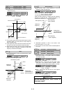
This function switches the frequency setting method
set in function codes F01 and C30 by an external
digital input signal.
This is the reverse-logic of setting value
"11"(Frequency setting 2/Frequency setting 1
[Hz2/Hz1]).
Set value input signal
35
Frequency setting method selected
off
C30 FREQ CMD2
on
F01 FREQ CMD1
Note: It can not be used with set value "11"
simultaneously. When the set value "11" and "35" are
selected, "Er6" is displayed.
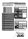
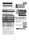
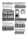
Setting at factory shipment
Digital
input
Set
value
Description
Terminal X1
0 Multistep frequency selection [SS1]
Terminal X2
1 Multistep frequency selection [SS2]
Terminal X3
2 Multistep frequency selection [SS4]
Terminal X4
3 Multistep frequency selection [SS8]
Terminal X5
4
Acceleration and deceleration selection [RT1]
Terminal X6
5
Acceleration and deceleration selection [RT2]
Terminal X7
6 Self-hold selection [HLD]
Terminal X8
7 Coast-to-stop command [BX]
Terminal X9
8 Alarm reset [RST]
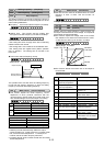
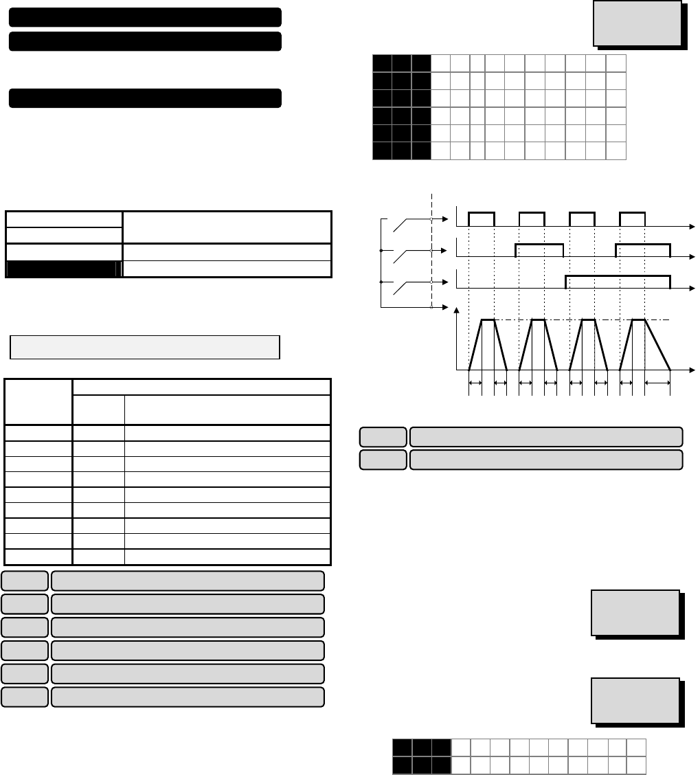
Acceleration time 1 (F07) and deceleration time 1 (F08)
as well as three other types of acceleration and
deceleration time can be selected.
The operation and setting ranges are the same as those
of acceleration time 1 and deceleration time 1. See
explanations for F07 and F08.
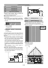
For switching acceleration and deceleration times, select
any two terminals from terminal X1 (function selection) in
E01 to terminal X9 (function selection) in E09 as
switching signal input terminals. Set "4" (acceleration
and deceleration time 1) and "5" (acceleration and
deceleration time 2) to the selected terminals and input a
signal to each terminal to switch acceleration and
deceleration times. Switching is possible during
acceleration, deceleration, or constant-speed operation.
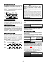
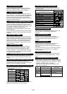
Example: When 4 and 5 are set to terminals X2 and X3:
ON
Time
ON
ON
FWD
(REV)
X2
X3
P24
Operation
Output
frequency
Maximum
frequency
Accel
time
1
Decel
time
1
Accel
time
2
Decel
time
2
Accel
time
3
Decel
time
3
Accel
time
4
Decel
time
4
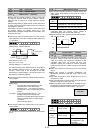
This function is used to switch the torque limit level set
in F40 and F41 by an external control signal. Input an
external signal by selecting any of the control input
terminals (X1 to X9) as torque limit 2/torque limit 1
(value 14) in E01 to E09.
The motor tuning (P04 / A13) should be set to "2" for
this function is valid.
Maximum compensation frequency during braking torque limit
is set by U01.
The operation mode is set by U60 when the setting
value is "0%: Regeneration avoidance at deceleration".
The detail is referred to the U01, U60.
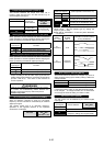
E 1 6 DRV T R Q 2
E 1 7 BRK T R Q 2
E16
Torque limiter 2 (driving)
Torque limiter 2 (braking) E17
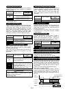
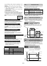
Settings when shipped from the factory
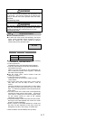
E10 Acceleration time 2
E11 Deceleration time 2
E12 Acceleration time 3
E13 Deceleration time 3
E14 Acceleration time 4
E15 Deceleration time 4
E 1 0 ACC T I M E 2
E 1 1 DEC T I M E 2
E 1 2 ACC T I M E 3
E 1 3 DEC T I M E 3
E 1 4 ACC T I M E 4
E 1 5 DEC T I M E 4
Line speed control Cancellation [Hz/LSC]
Line speed frequency memory [LSC-HLD]
Frequency setting 1 / Frequency setting 2 [Hz1/Hz2]