


2-13
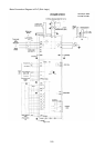
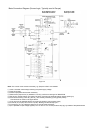
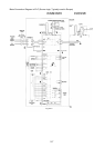
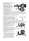
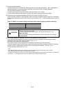
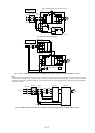
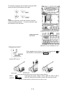
2-3-3 Connecting the control terminals
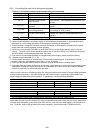
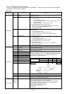
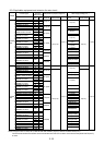
Table 2-3-3 lists the functions of the control circuit terminals. A control circuit terminal should be connected
according to the setting of its functions.
Table 2-3-3
Terminal
Classification
symbol
Terminal name Function
13 Potentiometer power
supply
Used for +10V DC power supply for frequency setting POT (variable
resistor of 1 to 5kΩ)
12 Voltage input
① Frequency is set according to the analog input voltage supplied from
an external circuit.
- 0 to +10V DC/0 to 100%
- Reversible operation using positive and negative signals:0 to +/-
10V DC/0 to 100%
- Reverse operation: +10 to 0V DC/0 to 100%
② The feedback signal for PID control is input.
③ The analog input value from the external circuit is used for torque
control. (P11S does not support this function.)
* Input resistance: 22kΩ
V2 Voltage input Frequency is set according to the analog input voltage supplied from an
external circuit
- 0 to +10V DC/0 to 100%
- Reverse operation:+10 to 0V DC/0 to 100%
* It can be used only one terminal "V2" or "C1" alternatively
* Input resistance:22kΩ
C1 Current input
① Frequency is set according to the analog input current supplied from
an external circuit.
- 4 to 20mA DC/0 to 100%
- Reverse operation:20 to 4mA DC/0 to 100%
② The feedback signal for PID control is input.
③ PTC thermistor input
* It can be used only one terminal "V2" or "C1" alternatively.
* Input resistance:250Ω
Analog input
11 Analog input common Common terminal for analog input signals
FWD Forward operation/stop
command
Used for forward operation (when FWD-CM is on) or deceleration and
stop (when FWD-CM is off)
REV Reverse operation/stop
command
Used for reverse operation (when REV-CM is on) or deceleration and
stop (when REV-CM is off)
X1 Digital input 1
X2 Digital input 2
X3 Digital input 3
X4 Digital input 4
X5 Digital input 5
X6 Digital input 6
X7 Digital input 7
X8 Digital input 8
X9 Digital input 9
The coast-to-stop command, external alarm, alarm reset, multistep
frequency selection, and other functions (from an external circuit) can be
assigned to terminals X1 to X9. For details, see "Setting the Terminal
Functions E01 to E09" in Section 5.2, "Details of Each Function."
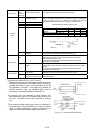
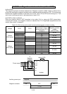
<Specifications of digital input circuit>
*
Item min. typ. max.
ON level 2V - 2V Operating voltage
OFF level 22V 24V 27V
Operating current at ON level - 3.2mA 4.5mA
Allowable leakage current at OFF level - - 0.5mA
CM Common terminal Common terminal for Digital input and FMP terminals
P24 Control Unit power Supply +24VDC power supply for control input. Maximum output current 100mA
Digital input
PLC PLC signal power Used to connect power supply for PLC output signals (rated voltage
24(22 to 27) V DC) at source logic operation.
Analog output
FMA
(11:
Common
terminal)
Analog monitor Outputs monitor signal using analog DC voltage 0 to +10V DC.
The meaning of this signal is one of the following:
-Output frequency (before slip compensation) -Power consumption
-Output frequency (after slip compensation) -PID feedback value
-Output current -PG feedback value
-Output voltage -DC link circuit voltage
-Output torque -Universal AO
-Load factor
*Connectable impedance:5kΩ minimum