


4-1
4. Keypad Panel
The keypad panel has various functions for specifying operations such as keypad operation (frequency
setting, run/stop command), confirming and changing function data, confirming status, and copying.
Review the use of each function before commencing running.
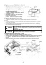
The keypad panel can also be removed or inserted during running. However, if the keypad panel is
removed during a keypad panel operation (e.g., run/stop, frequency setting), the inverter stops and outputs
an alarm.
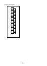
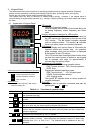
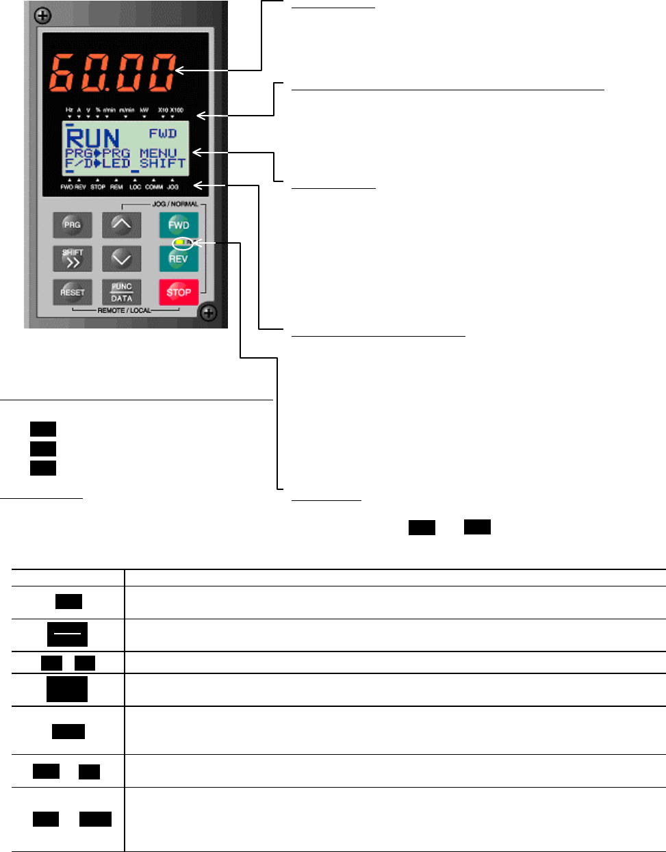
4-1 Appearance of Keypad Panel
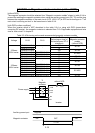
LED monitor:
Four-digit 7-segment display
Used to display various items of monitored data such
as setting frequency, output frequency and alarm
code.
Auxiliary information indication for LED monitor
:
Selected units or multiple of the monitored data (on
the LED monitor) are displayed on the top line of the
LCD monitor. The symbol indicates selected
units or multiple number. The symbol ▲ indicates
there is an upper screen not currently displayed.
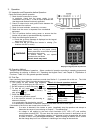
LCD monitor
:
Used to display such various items of information as
operation status and function data. An operation
guide message, which can be scrolled, is displayed
at the bottom of the LCD monitor.
This LCD monitor has a backlight feature which turns
on when the control power is applied or any keypad
key is pressed, and stays on approximately 5
minutes after the last key stroke.
Indication on LCD monitor
:
Displays one of the following operation status:
FWD: Forward operation REV: Reverse operation
STOP: Stop
Control keys (valid during keypad panel operation):
Used for inverter run and stop
: Forward operation command
: Reverse operation command
: Stop command
Operation keys
:
Used for screen switching, data change,
frequency setting, etc.
Displays the selected operation mode:
REM: Terminal block LOC: Keypad panel
COMM: Communication terminal
JOG: Jogging mode
The symbol ▼ indicates there is a lower screen not
currently displayed.
RUN LED
:
Indicates that an operation command was input by
pressing the or key.
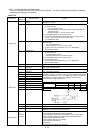
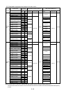
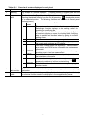
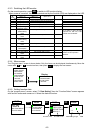
Table 4-1-1 Functions of operation keys
Operation key Main function
Used to switch the current screen to the menu screen or switch to the initial screen in
the operation/trip mode.
Used to switch the LED monitor or to determine the entered frequency, function code,
or data.
,
Used to change data, move the cursor up or down, or scroll the screen
Used to move the cursor horizontally at data change. When this key is pressed with
the up or down key, the cursor moves to the next function block.
Used to cancel current input data and switch the displayed screen. If an alarm
occurs, this key is used to reset the trip status (valid only when the alarm mode initial
screen is displayed).
+
Used to switch normal operation mode to jogging operation mode or vice versa. The
selected mode is displayed on the LCD monitor.
+
Switches operation mode (from keypad panel operation mode to terminal block
operation mode or reverse). When these keys are operated, function F01 data is also
switched from 0 to 1 or from 1 to 0. The selected mode is displayed on the LCD
indicator.
FWD
REV
REV
FED
STOP
FUNC
DATA
SHIFT
>>
∧
∨
∧
STOP
PRG
RESET
STOP
RESET