


5-45
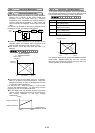
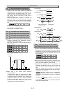
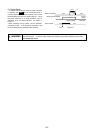
◆In case of F14 set value : 3.
The output frequency is lowered by the control by
which the DC voltage of the main circuit is kept
constant from the regeneration energy, so that the
inverter may continue operation when momentary
power failure occurs.
The response is adjusted with U23 and U24 at this
time.
◆Calculate the integral gain using the following formula.
value set23"U"
2
gainIntegral
16
=
[ms]
PI
calculator
H15
Set value
DC voltage of the
main circuit
Output frequency
command
|f
*
|
I gain:U23
P gain:U24
|f
*
|
0
Output frequency
command
|f
**
|
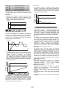
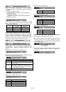
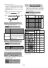
Input phase loss protection U48
◆This function selects operation of input phase loss or
power supply unbalance protection.
U 4 8 U S E R 4 8
Setting range : 0 to 2
Set value Operation
0 Active (without reactor (ACR/DCR))
1 Active (with reactor (ACR/DCR))
2 Inactive
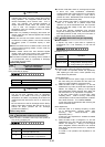
When "2" is set to U48, protection
operation of the inverter to input phase
loss or power supply voltage unbalance
does not work. If you use it as it is,
there is a possibility of damaging an
inverter.
Failure may result.
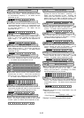
RS-485 protocol selection U49
◆The protocol of RS-485 communication is changed.
U 4 9 U S E R 4 9
Set value : 0, 1
Set value Operation
0 FGI-bus
1 Modbus-RTU
Instruction manual and specifications are prepared
about communicative details. Contact Fuji Electric.
Speed agreement /PG error(Detection width)U56
Speed agreement /PG error (Detection timer)
U57
PG error selection
U58
◆ These functions are effective for the option card
( OPC-G11S-PG,-PG2,-PGA ).
Refer to each manual.
U 5 6 U S E R 5 6
U 5 7 U S E R 5 7
U 5 8 U S E R 5 8
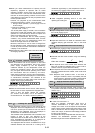
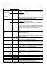
◆When function code F13 (electronic thermal)is set to 2,
both the type of the braking resistor and connection
circuit are set. Factory setting is set to nominal applied
resistor and the number of resistor is one. When the
power load capacities of resistor are increased, set the
factory setting properly
U 5 9 U S E R 5 9
Setting range : 0 to A8 (HEX)
Setting of ten’s digit ( type selection )
Set
value Type braking resistor
Resistance
[
Ω
]
Capacity
[W]
Duty
cycle
[%ED]
0
Standard applied resistor
- -
1 DB0.75-2C 100 200
2 DB2.2-2C 40 400
3 DB3.7-2C 33 400
4 DB5.5-2C 20 800
5 DB7.5-2C 15 900
6 DB0.75-4C 200 200
7 DB2.2-4C 160 400
8 DB3.7-4C 130 400
9 DB5.5-4C 80 800
A DB7.5-4C 60 900
10%
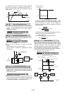
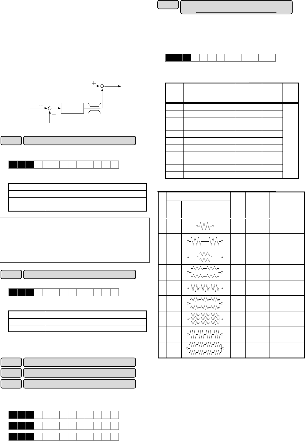
Setting of unit’s digit (connection circuit selection)
Braking-resistor
Set value
Use
number
Connection circuit
*1)
Duty
cycle
[%ED]
Synthetic
resistance
[
Ω
]
Power
consumption per
resistance
[comparatively]
01
DBP
10% R 100%
12
DBP
20% 2R 50%
22
DBP
20% (1/2)R 50%
34
DBP
40% R 25%
43
DBP
30% 3R 33%
56
DBP
50% (3/2)R 17%
69
DBP
50% R 11%
74
DBP
40% 4R 25%
88
DBP
50% 2R 12.5%
1) It is limited by the %ED value of the braking transistor
inside the inverter.
Braking - resistor function select
[30HP or less is corresponded]
U59
CAUTION
△
!