


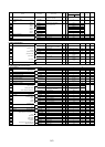

5-3
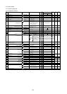
Factory setting
Func
No.
NAME LCD Display Setting range Unit
Min.
Unit
-30HP 40HP-
Change
during op
User
Set value
Remark
C20 JOG frequency C20 JOG Hz G11S:0.00 to 400.00Hz Hz 0.01 5.00 A
P11S:0.00 to 120.00Hz
C21 PATTERN(Mode select) C21 PATTERN 0,1,2 - - 0 NA
operation
C22 (Stage 1) C22 STAGE 1 Operation time:0.00 to 6000s s 0.01 0.00 F1 A
C23 (Stage 2) C23 STAGE 2 F1 to F4 and R1 to R4 0.00 F1 A
C24 (Stage 3) C24 STAGE 3 0.00 F1 A
C25 (Stage 4) C25 STAGE 4 0.00 F1 A
C26 (Stage 5) C26 STAGE 5 0.00 F1 A
C27 (Stage 6) C27 STAGE 6 0.00 F1 A
C28 (Stage 7) C28 STAGE 7 0.00 F1 A
C30 Frequency command 2 C30 FREQ CMD 2 0 to 11 - - 2 NA
C31 Offset adjust(terminal[12]) C31 BIAS 12 -100.0 to +100.0% % 0.1 0.0 A
C32 C32 GAIN 12 0.0 to +200.0% % 0.1 100.0 A
C33 Analog setting signal filter C33 REF FILTER 0.00 to 5.00s s 0.01 0.05 A
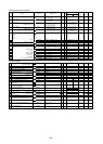
P:Motor Parameters
P01 Number of motor 1 poles P01 M1 POLES 2 to 14 - 2 4 NA
P02 Motor 1 (Capacity) P02 M1-CAP Up to 30[HP]: 0.01 to 60HP HP 0.01 Motor Capacity NA
40[HP]and above: 0.01 to 800HP
P03 (Rated current) P03 M1-Ir 0.00 to 2000A A 0.01 Motor rated current NA
P04 (Tuning) P04 M1 TUN1 0, 1, 2 - - 0 NA
P05 (On-line Tuning) P05 M1 TUN2 0, 1 - - 0 NA
P06 (No-load current) P06 M1-Io 0.00 to 2000A A 0.01 NA
Fuji STANDARD RATED
VALUE
P07 (%R1 setting) P07 M1-%R1 0.00 to 50.00% % 0.01 A
Fuji STANDARD RATED
VALUE
P08 (%X setting) P08 M1-%X 0.00 to 50.00% % 0.01 A
Fuji STANDARD RATED
VALUE
P09 Slip compensation control 1 P09 SLIP COMP1 0.00 to 15.00Hz Hz 0.01 0.00 A
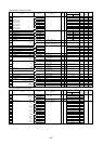
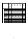
H:High Performance Functions
H03 Data initializing H03 DATA INIT 0, 1 - - 0 NA
H04 Auto-reset (Times) H04 AUTO-RESET 0, 1 to 10 times - 1 0 A
H05 (Reset interval) H05 RESET INT 2 to 20s s 1 5 A
H06 Fan stop operation H06 FAN STOP 0, 1 - - 0 A
H07 ACC/DEC pattern (Mode select) H07 ACC PTN 0,1,2,3 - - 0 NA
H08 Rev. phase sequence lock H08 REV LOCK 0, 1 - - 0 NA
H09 Start mode H09 START MODE 0, 1, 2 - - 0 NA
H10 Energy-saving operation H10 ENERGY SAV 0, 1 - - G11S:0 A
P11S:1
H11 DEC mode H11 DEC MODE 0, 1 - - 0 A
H12 Instantaneous OC limiting H12 INST CL 0, 1 - - 1 NA
H13 Auto-restart (Restart time) H13 RESTART t 0.1 to 10.0s s 0.1 0.1 NA
H14 (Freq. fall rate) H14 FALL RATE 0.00 to 100.00Hz/s Hz/s 0.01 10.00 A
H15 (Holding DC voltage) H15 HOLD V 3ph 230V class: 200 to 300V V 1 230V class:235V A
3ph 460V class: 400 to 600V 460V class:470V
H16 (OPR command selfhold time) H16 SELFHOLD t 0.0 to 30.0s, 999 s 0.1 999 NA
H18 Torque control H18 TRQ CTRL G11:0, 1, 2, P11:0 - - 0 NA
H19 Active drive H19 AUT RED 0, 1 - - 0 A
H20 PID control (Mode select) H20 PID MODE 0, 1, 2 - - 0 NA
H21 (Feedback signal) H21 FB SIGNAL 0, 1, 2, 3 - - 1 NA
H22 (P-gain) H22 P-GAIN 0.01 to 10.00 times - 0.01 0.1 A
H23 (I-gain) H23 I-GAIN 0.0 , 0.1 to 3600s s 0.1 0.0 A
H24 (D-gain) H24 D-GAIN 0.00s , 0.01 to 10.0s s 0.01 0.00 A
H25 (Feedback filter) H25 FB FILTER 0.0 to 60.0s s 0.1 0.5 A
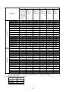
H26 PTC thermistor (Mode select) H26 PTC MODE 0, 1 0 A
H27 (Level) H27 PTC LEVEL 0.00 to 5.00V V 0.01 1.60 A
H28 Droop operation H28 DROOP G11:-9.9 to 0.0Hz, P11:0.0 (Fixed.) Hz 0.1 0.0 A
H30 Serial link (Function select) H30 LINK FUNC 0, 1, 2, 3 - - 0 A
H31 Modbus-RTU (Address) H31 ADDRESS 0 (broadcast), 1 to 247 - 1 1 NA
H32 (Mode select on no response error) H32 MODE ON ER 0, 1, 2, 3 - - 0 A
H33 (Timer) H33 TIMER 0.0 to 60.0s s 0.1 2.0 A
H34 (Baud rate) H34 BAUD RATE 0, 1, 2, 3 - - 1 A
H35 (Data length) H35 LENGTH 0 (8-bit fixed) - - 0 A
H36 (Parity check) H36 PARITY 0, 1, 2 - - 0 A
H37 (Stop bits) H37 STOP BITS 0(2bit), 1(1bit) - - 0 A
H38 (No response error detection time) H38 NO RES t 0 (No detection), 1 to 60s s 1 0 A
H39 (Response interval) H39 INTERVAL 0.00 to 1.00s s 0.01 0.01 A