


5-43
This function becomes effective, when the torque limit
(brake) is used. The inverter controls to increase the
output frequency so that torque calculations do not
exceed the torque limit (brake) setting ( F41 or E17).
(When F41 or E17 is set to 999, it becomes invalid.)
This function sets the increment of upper limit for
output frequency.
When the regeneration avoidance is selected, the
resurrection ability can be improved by raising the
increment of upper limit. However, the output frequency
of the inverter is limited at the frequency limit(high):
F15.
U 0 1 U S E R 0 1
Setting range : 0 to 65535
The set value "15" becomes 1Hz.
(The set value "1" becomes 1/15Hz)
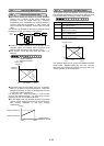
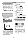
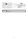
1st S-shape level at acceleration (start)U02
2nd S-shape level at acceleration (stop)U03
1st S-shape level at deceleration (start)U04
2nd S-shape level at deceleration (stop)U05
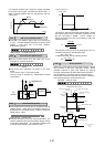
When "2" is set in the function code: H07, both
curvilinear acceleration and deceleration ranges of
S-shape can be set up arbitrarily.
The range is the ratio for maximum output frequency 1
(F03) or 2 (A01) .
U 0 2 U S E R 0 2
U 0 3 U S E R 0 3
U 0 4 U S E R 0 4
U 0 5 U S E R 0 5
Setting range : 1 to 50%
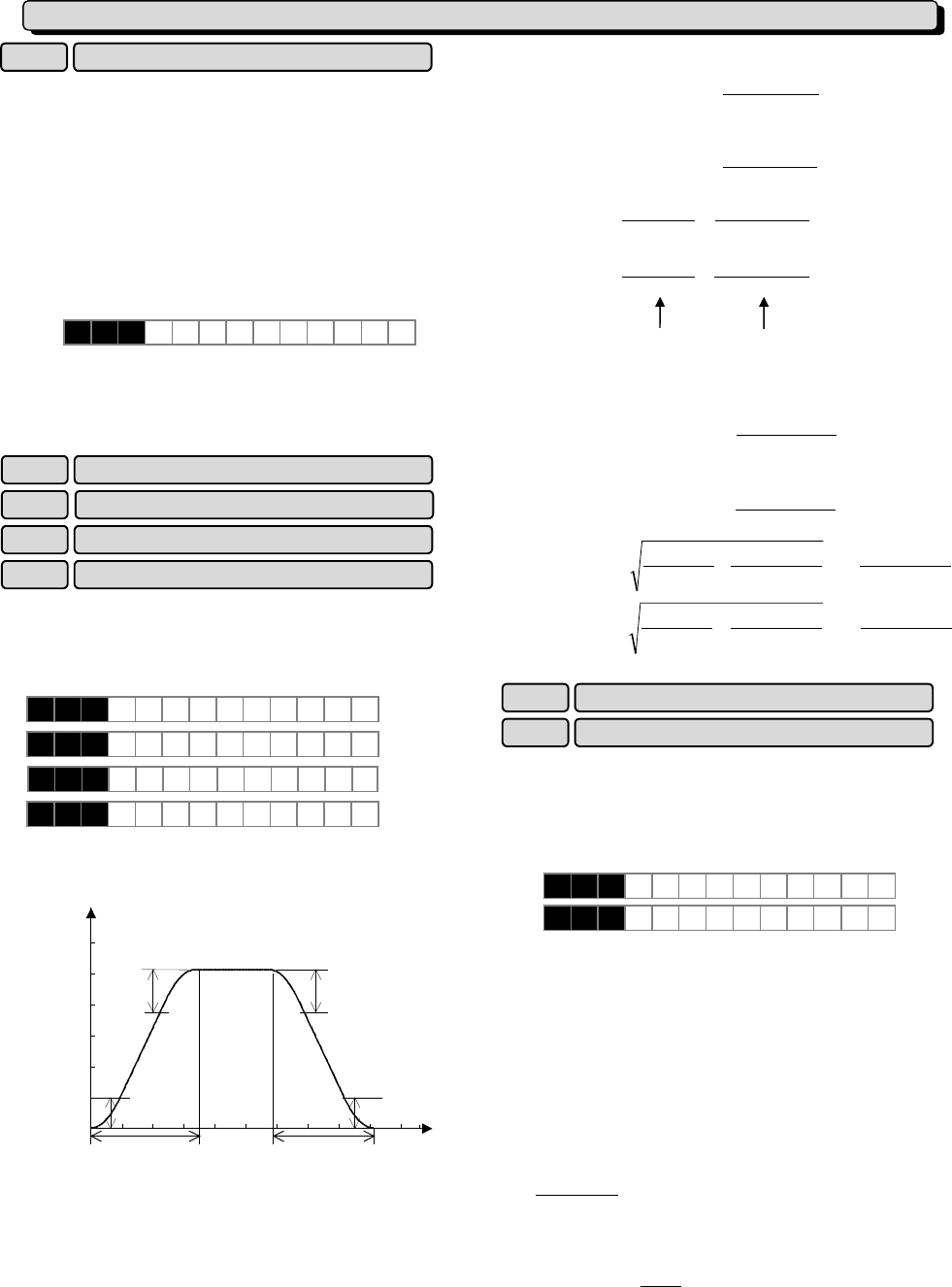
U05
f1
Output frequency
0
f[Hz]
t[s]
tdec
tacc
U03
U02
U04
f0
100% value of this function means maximum
frequency (fmax) .
Acceleration time “tacc” and deceleration time “tdec”
of upper figure become longer than the linear
acceleration time and deceleration time. When the set
acceleration time(F07,E10,E12,E14) is assumed to
be “Ta” and deceleration time(F08,E11,E13,E15) is
assumed to be “Td”, “tacc” and “tdec” can be
calculated by the following expressions.
- At acceleration,
100
03U02U
maxf|0f1f|
+
×≥−
or,
- At deceleration,
100
05U04U
maxf|0f1f|
+
×≥−
Ta)
100
03U02U
maxf
0f1f
(tacc ×
+
+
−
=
Td)
100
05U04U
maxf
0f1f
(tdec ×
+
+
−
=
- At acceleration,
100
03U02U
maxf|0f1f|
+
×<−
or,
- At deceleration,
100
05U04U
maxf|0f1f|
+
×<−
Ta
100
03U02U
03U02U
100
maxf
0f1f
2tacc ×
⎟
⎠
⎞
⎜
⎝
⎛
+
×
⎭
⎬
⎫
⎩
⎨
⎧
+
×
−
×=
Td
100
05U04U
05U04U
100
maxf
0f1f
2tdec ×
⎟
⎠
⎞
⎜
⎝
⎛
+
×
⎪
⎭
⎪
⎬
⎫
⎪
⎩
⎪
⎨
⎧
+
×
−
×=
Initial value of main DC link capacitor U08
Measured value of main DC link capacitorU09
Data for the life expectancy judgment of the capacitor
in main circuit is stored in this function. The electrical
discharge time of the capacitor can be measured
automatically, and the time of part replacement can be
confirmed according to the decrement rate from the
factory shipment.
U 0 8 U S E R 0 8
U 0 9 U S E R 0 9
Setting range : 0 to 65535
The electrical discharge time which is measured in the
factory shipment is set to function code U08 as a initial
value. This value is different in each inverter.
The electrical discharge time of the capacitor is
measured automatically, when the power supply is
turned off. And, the result is stored in function code
U09.
When the power supply is turned off under the
conditions as follows, decrement rate (%) to the factory
shipment can be measured.
Conditions
: which has been described to "*Estimation
of life expectancy based on maintenance
information" of the instruction manual "8-2 periodical
inspection".
The result of
100
08U
09U
×
is displayed in CAP=xxx.x%
of maintenance information. 85% becomes a standard
at the part replacement time.
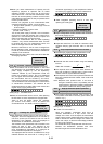
S-shape clause
linear Acceleration and
deceleration clause
U : User function
Maximum compensation frequency during braking torque limit
U01