


4-5
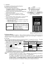
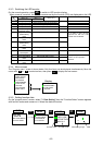
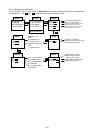
4-3-3 Switching the LED monitor
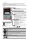
On the normal operation, press to switch to LED monitor display.
When power is turned on, the monitor contents set by the function (E43) are displayed on the LED.
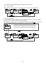
When stopping
(E44 = 0) (E44 = 1)
When running
(E44 =0,1)
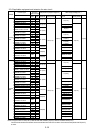
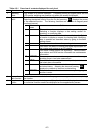
Unit Remarks
0 Setting frequency
Output frequency 1 (before slip compensation)
1 Setting frequency
Output frequency 2 (after slip compensation)
2 Setting frequency Setting frequency
Hz
3 Output current Output current A
4 Output voltage
(specified value)
Output voltage (specified value) V
5 Synchronous
speed setting
value
Synchronous speed r/min.
6 Line speed setting
value
Line speed m/min.
7 Load rotation
speed setting
value
Load rotation speed r/min.
For 4 digits or more, the last
digits are cut, with x10, x100
marked on the indicator.
8 Torque calculation
value
Torque calculation value %
± indication
9 Power
consumption
Power consumption kW
10 PID setting value PID setting value
−
11 PID remote setting
value
PID remote setting value
−
12 PID feedback
value
PID feedback value
−
Displayed only when PID is
effective in PID operation
selection.
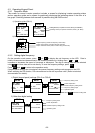
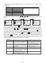
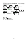
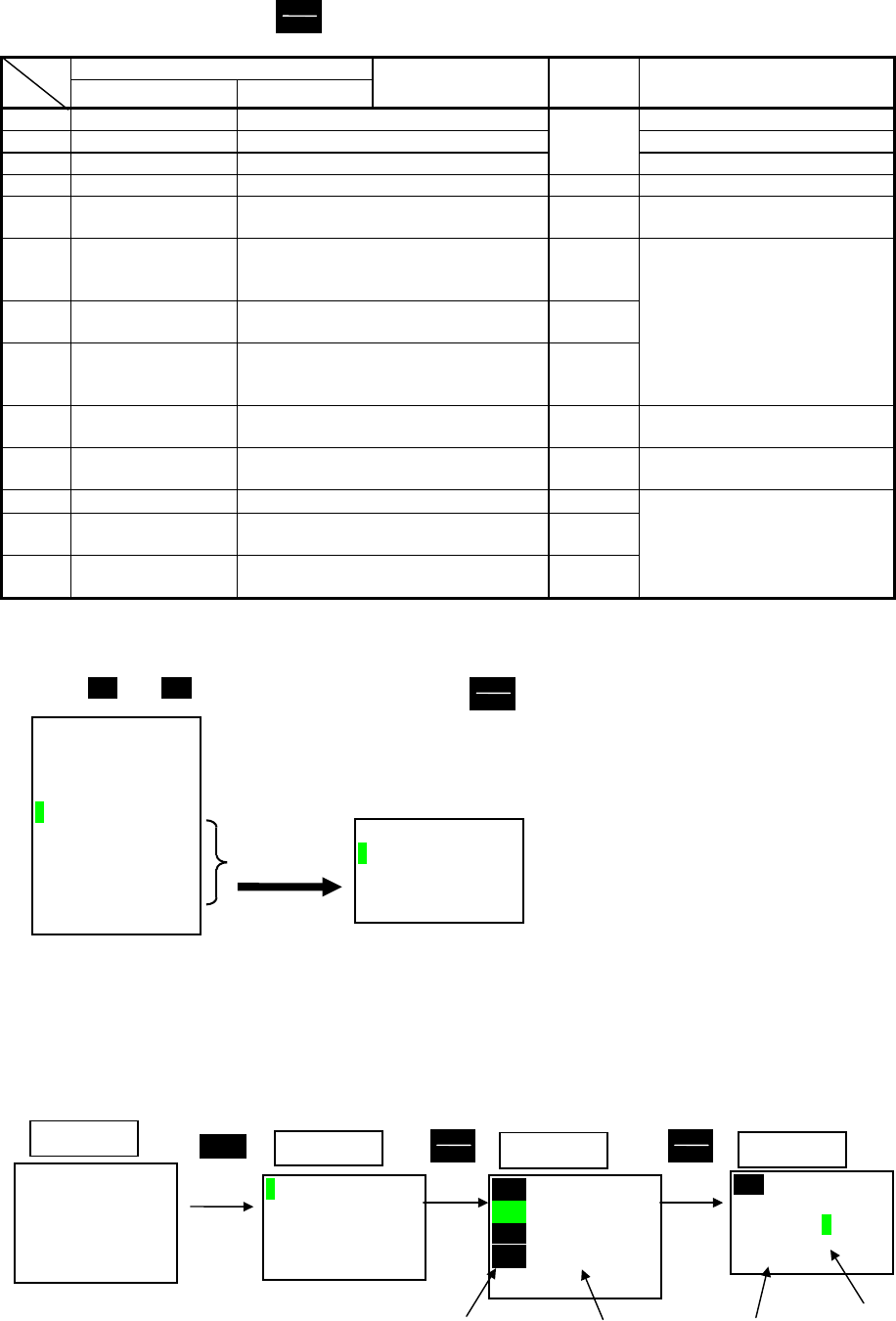
4-3-4 Menu screen
The “Program menu” screen is shown below. Only four items can be displayed simultaneously. Move the
cursor with or to select an item, then press to display the next screen.
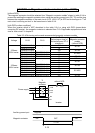
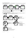
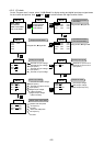
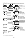
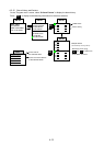
4-3-5 Setting function data
On the “program menu” screen, select "1. Data Setting" then the “Function Select” screen appears
with function codes and names on it. Select the desired function.
Function code Function name Data setting range
Data
E43
1.DATA SETTING
2.DATA CHECK
3.OPR MNTR
4.I/O CHECK
⇒
5.MAINTENANC
6.LOAD FCTR
7.ALM INF
8.ALM CAUSE
9.DATA COPY
4.I/O CHECK
⇒
5.MAINTENANC
6.LOAD FCTR
7.ALM INF
Display
F01FREQ COM 1
0
0 − 11
F00DATA PRTC
F01FREQ COM 1
F02OPR METHOD
F03MAX Hz-1
RUN
PRG
⇒
PRG MENU
F/D
⇒
LED SHIFT
60.00
⇒
1.DATA SETTING
2.DATA CHECK
3.OPR MNTR
4.I/O CHECK
60.00
60.00
60.00
PRG
FUNC
DATA
FUNC
DATA
∧
∨
FUNC
DATA
FUNC
DATA